Features: ` 5.0, 3.3, OR 3.0V OPERATING VOLTAGE
` SERIAL INTERFACE SUPPORTS I2C BUS (400kHz)
` NVRAM SUPERVISOR FOR EXTERNAL LPSRAM
` 2.5 TO 5.5V OSCILLATOR OPERATING VOLTAGE
` AUTOMATIC SWITCH-OVER AND DESELECT CIRCUITRY
` CHOICE OF POWER-FAIL DESELECT VOLTAGES
M41ST87Y: VCC = 4.75 to 5.5V;
THS Bit = '1': 4.50V VPFD 4.75V
VCC = 4.5 to 5.5V;
THS Bit = '0': 4.20V VPFD 4.50V
M41ST87W: VCC = 3.0 to 3.6V;
THS Bit = '1': 2.8V VPFD 3.0V
VCC = 2.7 to 3.6V;
THS Bit = '0': 2.55V VPFD 2.70V
` TWO INDEPENDENT POWER-FAIL COMPARATORS (1.25V REFERENCE)
` COUNTERS FOR TENTHS/HUNDREDTHS OF SECONDS, SECONDS, MINUTES, HOURS, DAY, DATE, MONTH, YEAR, AND
CENTURY
` 128 BYTES OF GENERAL PURPOSE RAM
` PROGRAMMABLE ALARM AND
INTERRUPT FUNCTION (VALID EVEN DURING BATTERY BACK-UP MODE)
` PROGRAMMABLE WATCHDOG TIMER
` UNIQUE ELECTRONIC SERIAL NUMBER (8-BYTE)
` 32kHz FREQUENCY OUTPUT AVAILABLE UPON POWER-ON
` MICROPROCESSOR POWER-ON RESET
` BATTERY LOW FLAG
` ULTRA-LOW BATTERY SUPPLY CURRENT OF 500nA (TYP) Pinout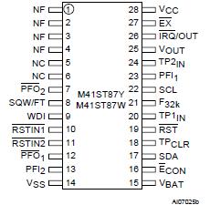 Specifications
|
Symbol |
Parameter |
Value |
Unit |
|
TSTG |
Storage Temperature (VCC Off, Oscillator Off) |
40 to 85 |
|
|
TSLD(1) |
Lead Solder Temperature for 10 seconds |
240 |
|
|
|
Input or Output Voltages |
0.3 to VCC +0.3 |
V |
|
VCC |
Supply Voltage |
M41ST84Y |
0.3 to 7 |
V |
| M41ST84W |
0.3 to 4.6 |
V |
|
IO |
Output Current |
20 |
mA |
|
PD |
Power Dissipation |
1 |
W |
Note: 1. Reflow at peak temperature of 240°C (total thermal budget not to exceed 180°C between 90 to 150 seconds).
CAUTION: Negative undershoots below 0.3V are not allowed on any pin while in the Battery Back-up mode.DescriptionThe M41ST87Y/W Serial TIMEKEEPER®/Controller SRAM is a low power 1280-bit, static CMOS SRAM organized as 160 bytes by 8 bits. A built-in 32.768 kHz oscillator (internal crystal-controlled) and 8 bytes of the SRAM (see Table 6., page 23) are used for the clock/calendar function and are configured in binary coded decimal (BCD) format. An additional 11 bytes of RAM M41ST87Y/W provide calibration, status/control of Alarm, Watchdog, Tamper, and Square Wave functions. 8 bytes of ROM and finally 128 bytes of User RAM are also provided. Addresses and data are transferred serially via a two line, bi-directional I2C interface. The built-in address register is incremented automatically after each WRITE or READ data byte. The M41ST87Y/ W has a built-in power sense circuit which detects power failures and automatically switches to the battery supply when a power failure occurs. The energy needed to sustain the SRAM and clock operations of M41ST87Y/W can be supplied by a small lithium buttoncell supply when a power failure occurs.
Functions of M41ST87Y/W available to the user include a non-volatile, time-of-day clock/calendar, Alarm interrupts, Tamper Detection, Watchdog Timer, and programmable Square Wave output. Other features include a Power-On Reset as well as two additional debounced inputs (RSTIN1 and RSTIN2) M41ST87Y/W can also generate an output Reset (RST). TheController SRAM is a low power 1280-bit, static CMOS SRAM organized as 160 bytes by 8 bits. A built-in 32.768 kHz oscillator (internal crystal-controlled) and 8 bytes of the SRAM (see Table 6., page 23) are used for the clock/calendar function and are configured in binary coded decimal (BCD) format. An additional 11 bytes of RAM provide calibration, status/control of Alarm, Watchdog, Tamper, and Square Wave functions. 8 bytes of ROM and finally 128 bytes of User RAM are also provided. Addresses and data are transferred serially via a two line, bi-directional I2C interface. The built-in address register is incremented automatically after each WRITE or READ data byte. The M41ST87Y/ W has a built-in power sense circuit which detects power failures and automatically switches to the battery supply when a power failure occurs. The energy needed to sustain the SRAM and clock operations can be supplied by a small lithium buttoncell supply when a power failure occurs.
Functions of M41ST87Y/W available to the user include a non-volatile, time-of-day clock/calendar, Alarm interrupts, Tamper Detection, Watchdog Timer, and programmable Square Wave output. Other features include a Power-On Reset as well as two additional debounced inputs (RSTIN1 and RSTIN2) M41ST87Y/W can also generate an output Reset (RST). The eight clock address locations contain the century, year, month, date, day, hour, minute, second and tenths/hundredths of a second in 24 hour BCD format. Corrections for 28, 29 (leap year), 30 and 31 day months are made automatically.
M41ST87Y/W Security Features
Two fully independent Tamper Detection Inputs of M41ST87Y/W allow monitoring of multiple locations within the system. Programmable bits provide both, "Normally Open" and "Normally Closed" switch monitoring. Time Stamping of the tamper event is automatically provided. There is also an option allowing data stored in either internal memory (128 bytes), and/ or external memory to be cleared, protecting sensitive information in the event tampering occurs. By embedding the 32kHz crystal in the package, the clock is completely isolated from external tampering. An Oscillator Fail Bit (OF) is also provided to ensure correct operation of the oscillator. The M41ST87Y/W is supplied in a 28-pin, 300mil SOIC M41ST87Y/W package (MX) which includes an embedded 32kHz crystal.
The SOIC package of M41ST87Y/W is shipped in plastic anti-static tubes or in Tape & Reel form.
The 300mil, embedded crystal SOIC M41ST87Y/W requires only a user-supplied battery to provide non-volatile operation.

 M41ST87Y Data Sheet