Features: • Allows safe board removal and insertion from a live backplane
• Accurate (<1.5%) internal voltage reference for fault detection and precision timing
• Programmable foldback current limiting
• Programmable circuit breaker current limiting
• Auto restart option for all faults
• Adjustable Undervoltage lockout thresholds
• Adjustable Overvoltage protection threshold
• Adjustable Power Good delay
• Configurable Power Good output polarity
• Low-side drive of an external N-channel FETPinout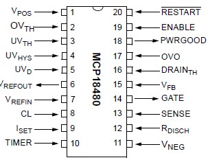 Specifications
| Number of Outputs | 1 |
| Vpos to Vneg Differential Voltage (V) Min Value | -0.3 to +15.0 V |
| Over Voltage Lockout (OVLO) | adjustable threshold |
| Power GOOD | adjustable polarity/adjustable delay |
| Int/Ext FET | External |
| Junction Temp. Range (°C) | -40°C to +85°C |
| Number of Outputs |
1 |
| Vpos to Vneg Differential Voltage (V) Min Value |
-0.3 to +15.0 V |
| Over Voltage Lockout (OVLO) |
adjustable threshold |
| Power GOOD |
adjustable polarity/adjustable delay |
| Int/Ext FET |
External |
| Junction Temp. Range (°C) |
-40°C to +85°C |
Ambient Temperature under bias........ 40°C to +85°C
Storage Temperature ........................ 65°C to +150°C
Voltage on VPOS with respect to VNEG -0.3V to +15.0V Voltage on DVTH, UVTH, VFB, OVO and UVHYS pins with respect to VNEG .....VNEG 0.3V to (VPOS + 0.3V) Voltage on VREFIN, CL, SENSE, DRAINTH, ENABLE and RESTART pins with respect to VNEG .................VNEG - 0.3V to 6V.
Total Power Dissipation (Note 1) .................... 800 mW
Max. Current out of VNEG pin.............................80 mA
Max. Current into VPOS pin ................................50 mA
Max. Output Current sunk by Gate pin...............80 mA
Max. Output Current sunk by VREFOUT pin ..........5 mA
Max. Output Current sunk by any other
Output pin.........................................................25 mA
Max. Output Current sourced by Gate pin ........200 A
Max. Output Current sourced by VREFOUT pin .....5 mA
Max. Output Current sourced by any other
Output pin...........................................................25 mA
Junction to Ambient, JA
(20 pin SSOP Package) Derating ...............108.1°C/W
Junction to Case, JC
(20 pin SSOP Package) Derating .................32.2°C/W
Lead Temperature, Soldering, 10 seconds ........ 300°C
† Notice: Stresses above those listed under "Maximum Ratings" may cause permanent damage to the device. This is
a stress rating only and functional operation of the device at those or any other conditions above those indicated in the operation listings of this specification is not implied. Exposure to maximum rating conditions for extended periods may affect device reliability.
Note 1: Power Dissipation is calculated as follows: PDIS = VDD x {IDD - IOH} + {(VDD-VOH) x IOH} + (VOL x IOL)
DescriptionMCP18480 is a 48V Hot Swap Controller with fully configurable features. This Hot Swap Controller have OVLO, UVLO protection features on top of Foldback Current Limiting and Circuit Breaker features. Although ideally suited optical switch backplanes, the MCP18480 can also be used in any 48V backplanes or whenever inrush current control is required.
The MCP18480 is a Hot Swap controller that allows boards to be safely removed or inserted from an active backplane using -48V.
When PCBs are inserted into a live backplane, highpeak or transient currents from the source are generated due to the charging of the bypass capacitors on the supply. The high transient currents can destroy connectors and capacitors. The high inrush current can pull the input voltage BUS down and reset the system.
The MCP18480 solves this problem by controlling the slew rate of the backplane voltage to the board so that these transients are eliminated. This allows boards to be removed and inserted without causing damage to connector pins and input bulk capacitors, in addition to preventing false resets to the other boards on the backplane.
The MCP18480 can be used in applications in several areas including:
• Telecom Line Cards
• Network Switches
• Network Routers and Servers
• Base Station Line Cards
• Power-Over-LAN
• Power-Over-MDI
• IP Phone Switches/Routers
• Mid-Span, Power-Over-MDI
Two forms of current limit are provided in the MCP18480. These are:
• Foldback
• Circuit breaker
The foldback current-limiting circuit of MCP18480 uses an external sense resistor and a voltage that is proportional to the external MOSFET's drain voltage. These are used to keep the MOSFET in its Safe Operating Area (SOA). If the device remains in current limit for a programmed time period, the external N-channel FET is turned off. The option of MCP18480 exists to configure the device to automatically restart after a programmed time delay. A programmable catastrophic current limit threshold shuts down the switch (circuit breaker) if excessive current is sensed due to a short-circuit condition.

 MCP18480 Data Sheet