NB100LVEP224

Features: • 20 ps Typical Output-to-Output Skew• 75 ps Typical Device-to- Device Skew• Maximum Frequency > 1 GHz• 650 ps Typical Propagation Delay• LVPECL Mode Operating Range: VCC = 2.375 V to 3.8 V with VEE = 0 V• NECL Mode Operating Range: VCC = 0 V with V...

product image

NB100LVEP224 Picture
SeekIC No. : 004432704 Detail

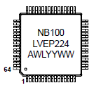
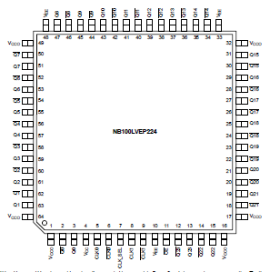
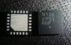
NB100LVEP224: Features: • 20 ps Typical Output-to-Output Skew• 75 ps Typical Device-to- Device Skew• Maximum Frequency > 1 GHz• 650 ps Typical Propagation Delay• LVPECL Mode Opera...

floor Price/Ceiling Price

Part Number:
NB100LVEP224
Supply Ability:
5000

Price Break

  • Qty
  • 1~5000
  • Unit Price
  • Negotiable
  • Processing time
  • 15 Days
Total Cost: $ 0.00

SeekIC Buyer Protection PLUS - newly updated for 2013!

  • Escrow Protection.
  • Guaranteed refunds.
  • Secure payments.
  • Learn more >>

Month Sales

268 Transactions

Rating

evaluate  (4.8 stars)

Upload time: 2024/4/28

Payment Methods

All payment methods are secure and covered by SeekIC Buyer Protection PLUS.

Notice: When you place an order, your payment is made to SeekIC and not to your seller. SeekIC only pays the seller after confirming you have received your order. We will also never share your payment details with your seller.
Product Details

Description


Features:

• 20 ps Typical Output-to-Output Skew
• 75 ps Typical Device-to- Device Skew
• Maximum Frequency > 1 GHz
• 650 ps Typical Propagation Delay
• LVPECL Mode Operating Range: VCC = 2.375 V to 3.8 V with VEE = 0 V
• NECL Mode Operating Range: VCC = 0 V with VEE = -2.375 V to -3.8 V
• Internal Input Pulldown Resistors
• Q Output will Default Low with Inputs Open or at VEE
• Thermally Enhanced 64-Lead LQFP
• CLOCK Inputs are LVDS-Compatible; Requires External 100 LVDS Termination Resistor


Pinout

  Connection Diagram


  Connection Diagram


Specifications

Symbol
Parameter
Condition 1
Condition 2
Rating
Unit
VCC
PECL Mode Power Supply
GEE = 0 V
6
V
VEE
NECL Mode Power Supply
GCC = 0 V
-6
V
VI
PECL Mode Input Voltage
NECL Mode Input Voltage
GEE = 0 V
GCC = 0 V
VI VCC
VI VEE
6 to 0
-6 to 0
V
V
TA
Operating Temperature Range
0 to +85
Tstg
Storage Temperature Range
−65 to +150
JA
Thermal Resistance (Junction−to−Ambient)
(See Application Information)
0 lfpm
500 lfpm
64 LQFP
64 LQFP
35.6
30
/W
/W
JC
Thermal Resistance (Junction−to−Ambient)
(See Application Information)
0 lfpm
500 lfpm
64 LQFP
64 LQFP
3.2
6.4
/W
/W
Tsol
Wave Solder
<2 to 3 sec @ 248°C
265

2. Maximum Ratings are those values beyond which device damage may occur.


Description

The NB100LVEP224 is a low skew 1-to-24 differential clock driver, designed with clock distribution in mind, accepting two clocksources into an input multiplexer. The part is designed for use in low voltage applications which require a large number of outputs to drive precisely aligned low skew signals to their destination. The two clock inputs are differential ECL/PECL and they are selected by the CLK_SEL pin. To avoid generation of a runt clock pulse when the NB100LVEP224 is enabled/disabled, the Output Enable ( OE ) is synchronous ensuring the outputs will only be enabled/disabled when they are already in LOW state (See Figure 4).

The NB100LVEP224 guarantees low output-to-output skew. The optimal design, layout, and processing minimize skew within a device and from lot to lot. In any differential output, the same bias and termination scheme is required. Unused output pairs should be left unterminated (open) to "reduce power and switching noise as much as possible." Any unused single line of a differential pair should be terminated the same as the used line to maintain balanced loads on the differential driver outputs. The wide VIHCMR specification allows both pair of CLOCK inputs to accept LVDS levels.

The NB100LVEP224, as with most other ECL devices, can be operated from a positive VCC supply in LVPECL mode. This allows the LVEP224 to be used for high performance clock distribution in +3.3 V or +2.5 V systems. Single-ended CLK input operation is limited to a VCC . 3.0 V in LVPECL mode, or VEE 3 -3.0 V in NECL mode. In a PECL environment, series or Thevenin line terminations are typically used as they require no additional power supplies. For more information on PECL terminations, designers should refer to Application Note AND8020/D.


Customers Who Bought This Item Also Bought

Margin,quality,low-cost products with low minimum orders. Secure your online payments with SeekIC Buyer Protection.
Isolators
Optoelectronics
Resistors
Test Equipment
Programmers, Development Systems
Cables, Wires - Management
View more