PinoutDescriptionThe S-24C01ADP is designed as a series of 2-wired, low power 1K-bit EEPROMs with a wide operating range. They are organized as 128-word x8-bit respectively. Each is capable of page write and sequential read.S-24C01ADP has seven features. (1)Low power consumption which means standb...
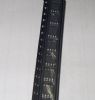
S-24C01ADP: PinoutDescriptionThe S-24C01ADP is designed as a series of 2-wired, low power 1K-bit EEPROMs with a wide operating range. They are organized as 128-word x8-bit respectively. Each is capable of page ...
SeekIC Buyer Protection PLUS - newly updated for 2013!
268 Transactions
All payment methods are secure and covered by SeekIC Buyer Protection PLUS.

The S-24C01ADP is designed as a series of 2-wired, low power 1K-bit EEPROMs with a wide operating range. They are organized as 128-word x8-bit respectively. Each is capable of page write and sequential read.
S-24C01ADP has seven features. (1)Low power consumption which means standby 1.0uA max and operating 0.4mA max at Vcc=5.5V and 0.3mA max at Vcc=3.3V. (2)Wide operating voltage range which would be 2.5V to 5.5V for write and 1.8V to 5.5V for read. (3)Its page write is 8 bytes. (4)Sequential read capable. (5)Endurance 10^5 cycles/word. (6)Data retention is 10 years. (7)1 Kbits. Those are all the main features.
Some absolute maximum ratings of S-24C01ADP have been concluded into several points as follow. (1)Its power supply voltage would be from -0.3V to 7.0V. (2)Its input voltage would be from -0.3V to Vcc+0.3V. (3)Its output voltage would be from -0.3V to Vcc. (4)Its storage temperature under bias would be from -50°C to 95°C. (5)Its storage temperature range would be from -65°C to 150°C. It should be noted that stresses above those listed in absolute maximum ratings may cause permanent damage to device.
Also some electrical characteristics of S-24C01ADP are concluded as follow. (1)Its current consumption READ would be max 0.4mA at f=100KHz and Vcc=4.5V to 5.5V and and would be max 0.3mA at f=100kHz and Vcc=2.5V to 4.5V. (2)Its current consumption PROGRAM would be max 2.0mA at f=100KHz and Vcc=4.5V to 5.5V and would be max 1.5mA at f=100kHz and Vcc=2.5V to 4.5V. (3)Its standby current consumption would be max 1.0uA at Vcc=4.5V to 5.5V and would be max 0.6uA at Vcc=2.5V to 4.5V. (4)Its input leakage current would be typ 0.1uA and max 1.0uA. (5)Its output leakage current would be typ 0.1uA and max 1.0uA. And so on. If you have any question or suggestion or want to know more information please contact us for details. Thank you!