Features: • Major Gauge 10-bit resolution Drive provides 0.35° resolution
Sine/Cosine outputs for 360° operation
0.2° accuracy typical throughout entire range
• Minor gauge drivers provide 0.35° resolution
112° operation
0.5° accuracy typical throughout entire range
• Serial Data Input
Supports interface from microcontrollers
Compatible with Philips SGD SA5775A and DGD SA5777A
• Serial Data Output
Permits the STGD to be wired in series using a common chip select to additional STGDs, SGDs, and DGDs
Permits fault status information to be returned to the microcontroller
• Over Voltage Protection, Over Temperature Protection and Low Standby Current Operation
Gauge drivers disabled when supply voltage exceeds specified operating voltage, protection to 40V.
Gauge drivers disabled when die temperature exceeds operating range
External switch may supply overvoltage protected battery supply to other devices operating off battery
• Thermally Enhanced SO-28 surface mount packageApplicationFigure 4 demonstrates the connections between the STGD, the microcontroller, and optionally additional gauge drivers such as the SGD and DGD. With an active high on the chip select input (CS), data is shifted into the STGD through DATAIN on the rising edge of SCLK. Several gauge drivers may be wired in series using a common chip select and clock line, when more than three gauges are needed. The DATAOUT pins are cascaded to the DATAIN pins of the following gauge drivers. Status information can be returned to the microcontroller via the ST pins of each gauge driver. These are open-drain, active low outputs, which may be wire OR'ed together to signal that a fault, such as a thermal shut down, has occurred within one of the gauge drivers. This pin may be connected to a microcontroller port pin for polling in software, or may be connected to an external interrupt input to cause entry into an interrupt service routine. The STGD, may also pass status information back to the microcontroller serially. The rising edge of chip select loads status information into the shift register for the first four bits that will be shifted out of the STGD by the shift clock. Figure 11 shows the data bits within the shift register. A low on the ST pin signals that one or more status bits have been set in the status register. A high indicates all status bits are reset. The status output bits include minor gauge over current, major gauge over current, thermal shutdown and RUN. Gauge data is captured in latches by the falling edge of the chip select.
Figure 5 shows the gauge connections to the STGD. The major gauge, G1, supports full 360° operation with two coils driven. The seven least significant bits of the gauge information are converted to an analog level by digital-to-analog converter. The display range is divided into eight sections, two sections per quadrant. The coils are driven with a Sine/Cosine approximation. The three most significant bits of gauge display information control the multiplexer to select which coil is fed by the DAC and which coil receives a fixed bias. The multiplexer also determines the polarity of the voltages supplied to the coils.
The minor gauges, G2 and G3, each have one coil driven by a DAC. The other coils of each gauge are wired in series with the switched battery supply to supply the bias. The switched battery supply is turned off during over voltage conditions. Only 9-bits of information are required for the minor gauges, however, 10-bits are shifted through the part to maintain compatibility with the SGD and DGD. Hence, all gauges, both major and minor, are supplied with 10-bit data for consistency.
Pinout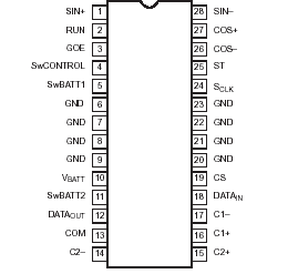 Specifications
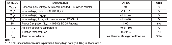 Description
The Serial Triple Gauge Driver (STGD)SA5778, is a single chip air core driver providing drive to one major gauge, and two minor gauges, for automotive applications such as Speedometer, Fuel, Temperature, Tachometer, Volts, and Oil pressure information display. The STGD SA5778 operates in conjunction with a microcontroller receiving serial data inputs, and can provide status back to the microcontroller either serially or via a status line. The protocol is compatible with the Philips Single Gauge Driver (SGD) and Dual Gauge Driver (DGD). The STGD SA5778 also includes a protected battery supply for external single Serial Gauge Drivers or Dual Gauge Drivers.

 SA5778 Data Sheet