SAF-C515C-8RM

Features: • Full upward compatibility with SAB 80C515A• 64k byte on-chip ROM (external program execution is possible)• 256 byte on-chip RAM• 2K byte of on-chip XRAM• Up to 64K byte external data memory• Superset of the 8051 architecture with 8 datapointers•...

product image

SAF-C515C-8RM Picture
SeekIC No. : 004484219 Detail

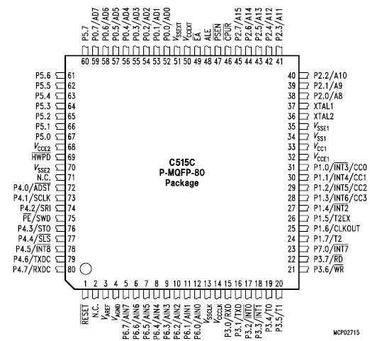
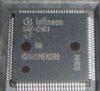
SAF-C515C-8RM: Features: • Full upward compatibility with SAB 80C515A• 64k byte on-chip ROM (external program execution is possible)• 256 byte on-chip RAM• 2K byte of on-chip XRAM• Up...

floor Price/Ceiling Price

Part Number:
SAF-C515C-8RM
Supply Ability:
5000

Price Break

  • Qty
  • 1~5000
  • Unit Price
  • Negotiable
  • Processing time
  • 15 Days
Total Cost: $ 0.00

SeekIC Buyer Protection PLUS - newly updated for 2013!

  • Escrow Protection.
  • Guaranteed refunds.
  • Secure payments.
  • Learn more >>

Month Sales

268 Transactions

Rating

evaluate  (4.8 stars)

Upload time: 2024/4/17

Payment Methods

All payment methods are secure and covered by SeekIC Buyer Protection PLUS.

Notice: When you place an order, your payment is made to SeekIC and not to your seller. SeekIC only pays the seller after confirming you have received your order. We will also never share your payment details with your seller.
Product Details

Description


Features:

• Full upward compatibility with SAB 80C515A
• 64k byte on-chip ROM (external program execution is possible)
• 256 byte on-chip RAM
• 2K byte of on-chip XRAM
• Up to 64K byte external data memory
• Superset of the 8051 architecture with 8 datapointers
• Up to 10 MHz external operating frequency (1s instruction cycle time at 6 MHz external clock)
• On-chip emulation support logic (Enhanced Hooks Technology TM)
• Current optimized oscillator circuit and EMI optimized design
• Eight ports : 48+1 digital I/O lines, 8 analog inputs
Quasi-bidirectional port structure (8051 compatible)
Port 5 selectable for bidirectional port structure (CMOS voltage levels)
• Full-CAN controller on-chip
256 register/data bytes are located in external data memory area
max.1 MBaud at 8-10 MHz operating frequency
• Three 16-bit timer/counters
Timer 2 can be used for compare/capture functions
• Full duplex serial interface with programmable baudrate generator (USART)
• SSC synchronous serial interface (SPI compatible)
Master and slave capable
Programmable clock polarity / clock-edge to data phase relation
LSB/MSB first selectable
2.5 MHz transfer rate at 10 MHz operating frequency
• Seventeen interrupt vectors, at four priority levels selectable
• Extended watchdog facilities
15-bit programmable watchdog timer
Oscillator watchdog
• Power saving modes
Slow-down mode
Idle mode (can be combined with slow-down mode)
Software power-down mode with wake-up capability through INT0 pin
Hardware power-down mode
• CPU running condition output pin
• ALE can be switched off
• Multiple separate VCC/VSS pin pairs
• P-MQFP-80-1 package
• Temperature Ranges : SAB-C515C-8R TA = 0 to 70°C
                                      SAF-C515C-8R TA = -40 to 85 °C
                                     SAH-C515C-8R TA = -40 to 110°C


Pinout

  Connection Diagram


Specifications

Ambient temperature under bias (TA) ................................ 40 to 110 °C
Storage temperature (Tstg) ......................................... 65 °C to 150 °C
Voltage on VCC pins with respect to ground (VSS) ............. 0.5 V to 6.5 V
Voltage on any pin with respect to ground (VSS) ...... 0.5 V to VCC +0.5 V
Input current on any pin during overload condition......... 10 mA to 10 mA
Absolute sum of all input currents during overload condition ...... I 100 mA I
Power dissipation................................................................................... TBD
Note: Stresses above those listed under "Absolute Maximum Ratings" may cause permanent damage of the device. This is a stress rating only and functional operation of the device at these or any other conditions above those indicated in the operational sections of this specification is not implied. Exposure to absolute maximum rating conditions for longer periods may affect device reliability. During overload conditions (VIN > VCC or VIN < VSS) the Voltage on VCC pins with respect to ground (VSS) must not exceed the values defined by the absolute maximum ratings.


Customers Who Bought This Item Also Bought

Margin,quality,low-cost products with low minimum orders. Secure your online payments with SeekIC Buyer Protection.
Power Supplies - Board Mount
Undefined Category
Motors, Solenoids, Driver Boards/Modules
RF and RFID
Optical Inspection Equipment
View more