Maximum Collector Emitter Saturation Voltage
: 0.4 V
Maximum Forward Diode Voltage
: 1.65 V
Maximum Power Dissipation
: 150 mW
Minimum Operating Temperature
: - 55 C
Packaging
: Tube
Maximum Operating Temperature
: + 100 C
Input Type
: DC
Package / Case
: PDIP-4
Current Transfer Ratio
: 600 %
Isolation Voltage
: 5300 Vrms
Maximum Collector Emitter Voltage
: 70 V
Maximum Collector Current
: 100 mA
Features: • High Current Transfer Ratios
at 5 mA: 50600%
at 1 mA: 60% typical (>13)
• Low CTR Degradation
• Good CTR Linearity Depending on Forward Current
• Isolation Test Voltage, 5300 VACRMS
• High Collector-Emitter Voltage, VCEO=70 V
• Low Saturation Voltage
• Fast Switching Times
• Field-Effect Stable by TRIOS (TRansparent IOn Shield)
• Temperature Stable
• Low Coupling Capacitance
• End-Stackable, .100"(2.54 mm) Spacing
• High Common-Mode Interference Immunity (Unconnected Base)
• Underwriters Lab File #52744
• VDE 0884 Available with Option 1
• SMD Option See SFH6106/16/56 Data SheetSpecificationsEmitter
Reverse Voltage...................................................................................... 6 V
DC Forward Current........................................................................... 60 mA
Surge Forward Current (tP 10s) ...................................................... 2.5 A
Total Power Dissipation................................................................... 100 mW
Detector
Collector-Emitter Voltage ..................................................................... 70 V
Emitter-Collector Voltage ....................................................................... 7 V
Collector Current................................................................................ 50 mA
Collector Current (tP 1 s)............................................................. 100 mA
Total Power Dissipation................................................................... 150 mW
Package
Isolation Test Voltage between Emitter and
Detector, refer to Climate DIN 40046,
part 2, Nov. 74.............................................................................. 5300 VAC
RMS
Creepage...........................................................................................7 mm
Clearance ..........................................................................................7 mm
Insulation Thickness between Emitter and Detector ......................0.4 mm
Comparative Tracking Index
per DIN IEC 112/VDE0 303, part 1........................................................175
Isolation Resistance
VIO=500 V, TA=25°C........................................................................1012W
VIO=500 V, TA=100°C......................................................................1011W
Storage Temperature Range................................................. 55 to +150°c
Ambient Temperature Range................................................ 55 to +100°C
Junction Temperature .........................................................................100°C
Soldering Temperature (max. 10 s. Dip Soldering
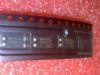
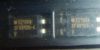
Distance to Seating Plane 1.5 mm)....................................................260°CDescriptionSFH615AA Optocoupler, Phototransistor Output, High Reliability, 5300 VRMS
The SFH615AA/AGB/AGR features a high current transfer ratio, low coupling capacitance and high isolation voltage. These couplers have a GaAs infrared emitting diode emitter, which is optically coupled to a silicon planar phototransistor detector, and is incorporated in a plastic DIP-4 package.
The SFH615AA is designed for signal transmission between two electrically separated circuits.
The SFH615AA is end-stackable with 2.54 mm spacing.
Creepage and clearance distances of >8 mm are achieved with option 6. This SFH615AA complies with IEC 950 (DIN VDE 0805) for reinforced insulation up to an operation voltage of 400 V RMS or DC.

 SFH615AA Data Sheet