Features: · To 3 A Output Rating
· Internal Sequencer for Microstepping Operation
· PWM Constant-Current Motor Drive
· Cost-Effective, Multi-Chip Solution
· 100 V, Avalanche-Rated NMOS
· Low rDS(on) NMOS Outputs
· Advanced, Improved Body Diodes
· Inputs Compatible with 3.3 V or 5 V Control Signals
· Sleep Mode
· Internal Clamp Diodes
ApplicationLayout.
The printed wirting board should use a heavy ground plane.
For optimum electrical and thermal performance, the driver should be soldered directly into the board.
The driver supply terminal, VBB, should be decoupled with an electrolytic capacitor (>47 F is recommended) placed as close to the device as possible. To avoid problems due to capacitive coupling of the high dv/dt switching transients, route the high-level, output traces away from the sensitive, low-level logic traces. Always drive the logic inputs with a low source impedance to increase noise immunity.
Grounding. A star ground system located close to the driver is recommended. The logic supply return and the driver supply return should be connected together at only a single point - the star ground.
Logic supply voltage, VDD. Transients at this terminal should be held to less than 0.5 V to avoid malfunctioning operation. Both VBB and VDD may be turned on or off separately.
Logic inputs. Unused logic inputs (CW/CCW, FULL/ HALF, or SYNC) must be connected to either ground or the logic supply voltage.
Current sensing. To minimize inaccuracies caused by ground-trace IR drops in sensing the output current level, the current-sense resistors, RS, should have an independent ground return to the star ground of the device. This path should be as short as possible. For low-value sense resistors, the IR drops in the printed wiring board sense resistor's traces can be significant and should be taken into account. The use of sockets should be avoided as they can introduce variation in RS due to their contact resistance.
PWM current control. The maximum value of current limiting (ITRIP) is set by the selection of RS and the voltage at the REF input with a transconductance function approximated by:
ITRIP = VREF/RS
The required VREF should not be less than 0.1 V. If it is, RS should be increased for a proportionate increase in VREF.
SpecificationsDriver Supply Voltage, VBB ............... 46 V
Load Supply Voltage, VM .................. 46 V
Output Current, IO
SLA7060M & SLA7065M .............. 1.0 A*
SLA7061M & SLA7066M .............. 2.0 A*
SLA7062M & SLA7067M .............. 3.0 A*
Logic Supply Voltage, VDD .............. 7.0 V
Logic Input Voltage Range,
VI ........................ -0.3 V to VDD+ 0.3 V
Sense Voltage, VS ..................... ±2.0 V†
Reference Input Voltage Range,
VREF ................... -0.3 V to VDD+ 0.3 V
Package Power Dissipation,
PD ...................................... See Graph
Junction Temperature, TJ ......... +150°C
Operating Temperature Range,
TA ........................... -20°C to +85°C
Storage Temperature Range,
TS ......................... -30°C to +150°C
* Output current rating may be limited by duty cycle, ambient temperature, and heat sinking. Under any set of conditions, do not exceed the specified current rating or junction temperature.
† Internal filtering provides protection against transients during the first 1 s of the current-sense pulse.
DescriptionCombining low-power CMOS logic with high-current, high-voltage power FET outputs, the Series SLA7062M translator/drivers provide complete control and drive for a two-phase unipolar stepper motor with internal fixed off time and pulse-width modulation (PWM) control of the output current in a power multi-chip module (PMCM™). There are no phase-sequence tables, high-frequency control lines, or complex interfaces to program.
The CMOS logic section SLA7062M provides the sequencing logic, direction, control, synchronous/asynchronous PWM operation, and a "sleep" function. The minimum CLOCK input is an ideal fit for applications where a complex P is unavailable or overburdened. TTL or LSTTL may require the use of appropriate pull-up resistors to ensure a proper input-logic high. For PWM current control, the maximum output current is determined by the user's selection of a reference voltage and sensing resistor. The NMOS outputs are capable of sinking up to 1, 2, or 3 A (depending on device) and withstanding 46 V in the off state. Clamp diodes provide protection against inductive transients. Special power-up sequencing is not required.
Half-, quarter-, eighth-, and sixteenth-step operation are externally selectable for the SLA7062M SLA7060/61/62M. Full-step (2 phase), half-, quarter-, and eighth-step operation are externally selectable for the SLA7065/66/67M. Two-phase drive energizes two adjacent phases in each detent position (AB-AB-AB-AB). This sequence mode offers an improved torque-speed product, greater detent torque, and is less susceptable to motor resonance. Half-step excitation alternates betweenthe one-phase and two-phase modes (A-AB-B-AB-A-AB-B-AB), providing an eight-step sequence.
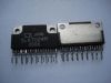
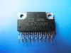
The Series SLA7062M is supplied in a 21-pin single in-line powertab package with leads formed for vertical mounting (suffix LF2102). The tab is at ground potential and needs no insulation. For high-current or high-frequency applications, external heat sinking may be required. This device is rated for continuous operation between -20°C and +85°C.

 SLA7062M Data Sheet