SN54ABT16543

Features: Members of the Texas Instruments WidebusE FamilyState-of-the-Art EPIC-II BE BiCMOS Design Significantly Reduces Power DissipationLatch-Up Performance Exceeds 500 mA Per JEDEC Standard JESD-17Typical VOLP (Output Ground Bounce) < 1 V at VCC = 5 V, TA = 25°CDistributed VCC and GND Pin C...

product image

SN54ABT16543 Picture
SeekIC No. : 004496291 Detail

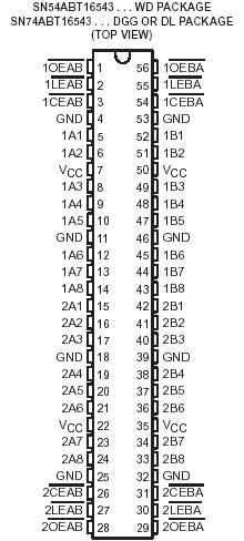
SN54ABT16543: Features: Members of the Texas Instruments WidebusE FamilyState-of-the-Art EPIC-II BE BiCMOS Design Significantly Reduces Power DissipationLatch-Up Performance Exceeds 500 mA Per JEDEC Standard JESD...

floor Price/Ceiling Price

Part Number:
SN54ABT16543
Supply Ability:
5000

Price Break

  • Qty
  • 1~5000
  • Unit Price
  • Negotiable
  • Processing time
  • 15 Days
Total Cost: $ 0.00

SeekIC Buyer Protection PLUS - newly updated for 2013!

  • Escrow Protection.
  • Guaranteed refunds.
  • Secure payments.
  • Learn more >>

Month Sales

268 Transactions

Rating

evaluate  (4.8 stars)

Upload time: 2025/12/24

Payment Methods

All payment methods are secure and covered by SeekIC Buyer Protection PLUS.

Notice: When you place an order, your payment is made to SeekIC and not to your seller. SeekIC only pays the seller after confirming you have received your order. We will also never share your payment details with your seller.
Product Details

Description


Features:

 Members of the Texas Instruments WidebusE Family
 State-of-the-Art EPIC-II BE BiCMOS Design Significantly Reduces Power Dissipation
 Latch-Up Performance Exceeds 500 mA Per JEDEC Standard JESD-17
Typical VOLP (Output Ground Bounce) < 1 V at VCC = 5 V, TA = 25°C
 Distributed VCC and GND Pin Configuration Minimizes High-Speed Switching Noise
 Flow-Through Architecture Optimizes PCB Layout
 High-Drive Outputs (32-mA IOH, 64-mA IOL)
Package Options Include Plastic 300-mil Shrink Small-Outline (DL) and Thin Shrink Small-Outline (DGG) Packages and 380-mil Fine-Pitch Ceramic Flat (WD) Package Using 25-mil Center-to-Center Spacings


Pinout

  Connection Diagram


Specifications

Supply voltage range, VCC . . . . . . . . . . . . . . . . . . . . . . . . . . . . . . . . . . . . . ..0.5 V to 7 V
Input voltage range, VI (except I/O ports) (see Note 1)  . . . . . . . . . . . . . . ..0.5 V to 7 V
Voltage range applied to any output in the high or power-off state, VO  . .0.5 V to 5.5 V
Current into any output in the low state, IO:SN54ABT16543 . . . . . . . . . . . . .         .96 mA
                                                                      SN74ABT16543 . . . . . . . . . . . . . . . .  128 mA
Input clamp current, IIK (VI < 0). . . . . . . . . . . . . . . . . . . . . . . . . . . . . . . . . . . . . . . 18 mA
Output clamp current, IOK (VO < 0) . . . . . . . . . . . . . . . . . . . . . . . . . . . . . . . . .   . . .50 mA
Package thermal impedance, qJA (see Note 2): DGG package  . . . . . . . . . . .     . . . 81°C/W
                                                                           DL package  . . . . . . . . . . . . . . . . ..74°C/W
Storage temperature range, Tstg . . . . . . . . . . . . . . . . . . . . . . . . . . . . . . . ..65°C to 150°C


Description

  The SN54ABT16543 16-bit registered transceivers contain two sets of D-type latches for temporary storage of data flowing in either direction. The SN54ABT16543 can be used as two 8-bit transceivers or one 16-bit transceiver. Separate latch-enable (LEAB or LEBA ) and output-enable (OEAB or OEBA ) inputs are provided for each register to permit independent control in either direction of data flow.

   The A-to-B enable (CEAB ) input must be low to enter data from A or to output data from B. If CEAB is low and LEAB is low, the A-to-B latches are transparent; a subsequent low-to-high transition of LEAB puts the A latches in the storage mode. With CEAB and OEAB both low, the 3-state B outputs are active and reflect the data present at the output of the A latches. Data flow from B to A is similar but requires using theCEBA , LEBA , and OEBA inputs. To ensure the high-impedance state during power up or power down, OE should be tied to VCC through a pullup resistor; the minimum value of the resistor is determined by the current-sinking capability of the driver. The SN54ABT16543 is characterized for operation over the full military temperature range of 55°C to 125°C. The SN54ABT16543 is characterized for operation from 40°C to 85°C.


Customers Who Bought This Item Also Bought

Margin,quality,low-cost products with low minimum orders. Secure your online payments with SeekIC Buyer Protection.
Computers, Office - Components, Accessories
Optoelectronics
Circuit Protection
Cable Assemblies
Optical Inspection Equipment
View more