Pinout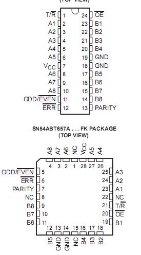 SpecificationsSupply voltage range, VCC. . . . . . . . . . . . . . . . . . . . . . . . . . . . . . . . . . . . . . . 0.5 V to 7 V
Input voltage range, VI(except I/O ports) (see Note 1) . . . . . . . . . . . . . . . . .0.5 V to 7 V
Voltage range applied to any output in the high or power-off state, VO. . . 0.5 V to 5.5 V
Current into any output in the low state, IO:SN54ABT657A. . . . . . . . . . . . . . . . . . . .. 96 mA
SN74ABT657A . . . . . . . . . . . . . . . . . . ..128 mA
Input clamp current, IIK(VI < 0). . . . .. . . . . . . . . . . . . . . . . . . . . . . . . . . . . . . . . . ....18 mA
Output clamp current, IOK (VO< 0) . . . . . . . . . . . . . . . . . . . . . . . . . . . . . . . . . . . . . 50 mA
Package thermal impedance, JA(see Note 2):DW package . . . . . . . . . . . . . . . . . . 81°C/W
NT package . . . . . . . . . . . . . . . . . . . 67°C/W
Storage temperature range, Tstg. . . . . . . . . . . . . . . . . . . . . . . . . . . . . . . . 65°C to 150°C
DescriptionThe, ABT657A transceivers have eight noninverting buffers with parity-generator/checker circuits and control signals. The transmit/receive (T/R</a>) input determines the direction of data flow. When T/R</a> is high, data flows from the A port to the B port (transmit mode); when T/R</a> is low, data flows from the B port to the A port (receive mode). When the output-enable (OE</a>) input is high, both the A and B ports of ABT657A are in the high-impedance state.
Odd or even parity is selected by a logic high or low level on the ODD/EVEN input. PARITY carries the parity-bit value; ABT657A is an output from the parity generator/checker in the transmit mode and an input to the parity generator/checker in the receive mode.
In the transmit mode, after the A bus ABT657A is polled to determine the number of high bits, PARITY is set to the logic level that maintains the parity sense selected by the level at ODD/EVEN</a>. For example, if ODD/EVEN</a> is low(even parity selected) and there are five high bits on the A bus, PARITY ABT657A is set to the logic high level so that an even number of the nine total bits (eight A-bus bits plus parity bit) are high.
In the receive mode, after the B bus ABT657A is polled to determine the number of high bits, the error (ERR</a>) output logic level indicates whether or not the data to be received exhibits the correct parity sense. For example, if ODD/EVEN</a> is high (odd parity selected), PARITY ABT657A is high, and there are three high bits on the B bus, ERR</a> is low, indicating a parity error.

 SN54ABT657A Data Sheet


