Features: This octal buffer and line driver is designed specifically to improve both the performance and density of 3-state memory address drivers, clock drivers, and bus-oriented receivers and transmitters. Taken together with the SN64BCT241 and SN64BCT244, these devices provide the choice of sel...
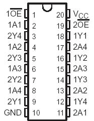
SN64BCT240: Features: This octal buffer and line driver is designed specifically to improve both the performance and density of 3-state memory address drivers, clock drivers, and bus-oriented receivers and tran...
SeekIC Buyer Protection PLUS - newly updated for 2013!
268 Transactions
All payment methods are secure and covered by SeekIC Buyer Protection PLUS.
PinoutSpecificationsSupply voltage range, VCC . . . . . . . . . . . . . . . . . . . . . . . . . . ...
US $1.18 - 1.72 / Piece
Buffers & Line Drivers Quad Bus Buffer Gate With 3-State Outputs
US $1.02 - 1.38 / Piece
Buffers & Line Drivers Quad Bus Buffer Gate With 3-State Outputs
This octal buffer and line driver is designed specifically to improve both the performance and density of 3-state memory address drivers, clock drivers, and bus-oriented receivers and transmitters. Taken together with the SN64BCT241 and SN64BCT244, these devices provide the choice of selected combinations of inverting and noninverting outputs, symmetrical active-low output-enable (OE) inputs, and complementary OE and OE inputs.
The SN64BCT240 is organized as two 4-bit buffers/line drivers with separate output-enable (OE) inputs. When OE is low, the device passes data from the A inputs to the Y outputs. When OE is high, the outputs are in the high-impedance state.
The SN64BCT240 is characterized for operation from 40°C to 85°C and 0°C to 70°C.

Supply voltage range, VCC . . . . . . . . . . . . . . . . . . . . . . .. . . . . . . . . 0.5 V to 7 V
Input voltage range, VI (see Note 1) . . . . . . . . . . . . . . . . . . . . .. . .0.5 V to 7 V
Voltage range applied to any output in the disabled or power-off state,
VO . . . . . . . . . . . . .. . . . . . . . . . . . . . . . . . . . . . . . . .. .. . . . . . . . .0.5 V to 5.5 V
Voltage range applied to any output in the high state, VO . . . . . .0.5 V to VCC
Current into any output in the low state, IO . . . . . . . . . . . . . . . . . . . . . . .128 mA
Operating free-air temperature range. . . . . . . . . . . . . . . . . . . . . . . . . . 127°C/W
Storage temperature range, Tstg . . . . . . . . . . . . . . . . . . . . . .. .65°C to 150°C
NOTES: 1. The input negative voltage rating may be exceeded if the input clamp current rating is observed.