Features: · Drop-In Improved Replacement for the PCA82C250 and PCA82C251
· Bus-Fault Protection of ±36 V
· Meets or Exceeds ISO 11898
· Signaling Rates(1) up to 1 Mbps
· High Input Impedance Allows up to 120 SN65HVD251 Nodes on a Bus
· Bus Pin ESD Protection Exceeds 14 kV HBM
· Unpowered Node Does Not Disturb the Bus
· Low Current Standby Mode . . . 200 µA Typical
· Thermal Shutdown Protection
· Glitch-Free Power-Up and Power-Down Bus Protection For Hot-Plugging
· DeviceNet Vendor ID # 806Application` CAN Data Buses
` Industrial Automation
DeviceNet™ Data Buses
Smart Distributed Systems (SDS™)
` SAE J1939 Standard Data Bus Interface
` NMEA 2000 Standard Data Bus Interface
` ISO 11783 Standard Data Bus InterfacePinout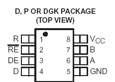 Specifications
|
|
SN65HVD251 |
|
Supply voltage range, VCC |
-0.3 V to 7V |
|
Voltage range at any bus terminal (CANH or CANL) |
-36 V to 36 V |
|
Transient voltage per ISO 7637, pulse 1, 2, 3a, 3b CANH, CANL |
±200 V |
|
Input voltage range, VI (D, Rs, or R) |
-0.3 V to VCC + 0.5 |
|
Electrostatic discharge |
Human Body Model (3) |
CANH, CANL and GND |
14 kV |
|
All pins |
6 kV |
|
Charged-Device Model (4) |
All pins |
1 kV |
|
Continuous total power dissipation |
(see Dissipation Rating
Table) |
|
Storage temperature range, Tstg |
-65C to 150°C |
|
Lead temperature 1,6 mm (1/16 inch) from case for 10 seconds |
260°C |
(1) Stresses beyond those listed under "absolute maximum ratings" may cause permanent damage to the device. These are stress ratings
only and functional operation of the device at these or any other conditions beyond those indicated under "recommended operating
conditions" is not implied. Exposure to absolute-maximum-rated conditions for extended periods may affect device reliability.
(2) All voltage values, except differential I/O bus voltages, are with respect to network ground terminal.
(3) Tested in accordance with JEDEC Standard 22, Test Method A114-A.
(4) Tested in accordance with JEDEC Standard 22, Test Method C101.
DescriptionThe SN65HVD251 is intended for use in applications employing the Controller Area Network (CAN) serial communication physical layer in accordance with the ISO 11898 Standard. The SN65HVD251 provides differential transmit capability to the bus and differential receive capability to a CAN controller at speeds up to 1 megabits per second (Mbps).
SN65HVD251 is designed for operation in harsh environments, the device features cross-wire, over-voltage and loss of ground protection to ±36 V. Also featured are over-temperature protection as well as -7 V to 12 V common-mode range, and tolerance to transients of ± 200 V. The transceiver SN65HVD251 interfaces the single-ended CAN controller with the differential CAN bus found in industrial, building automation, and automotive applications.
Rs, pin 8, SN65HVD251 provides for three different modes of operation: high-speed, slope control, or low-power mode. The high-speed mode of operation is selected by connecting pin 8 to ground, allowing the transmitter output transistors to switch as fast as possible with no limitation on the rise and fall slope. The rise and fall slope can be adjusted by connecting a resistor to ground at pin 8; the slope is proportional to the pin's output current. Slope control with an external resistor value of 10 kW gives ~ 15 V/us slew rate; 100 kW gives ~ 2 V/us slew rate.
If a high logic level is applied to the Rs pin 8, the SN65HVD251 enters a low-current standby mode during which the driver is switched off and the receiver remains active . The local protocol controller reverses SN65HVD251 this low-current standby mode when it needs to transmit to the bus.
The SN65HVD251 may be used in CAN, DeviceNet™ or SDS™ applications with the Texas Instruments' TMS320F241 and TMS320F243 DSPs with CAN 2.0B controllers.

 SN65HVD251 Data Sheet