Features: ` 8-Bit Bidirectional Data Storage Register With Full Parallel Access` Parallel Transfer Rates† Buffer Mode: Up to 475 Megatransfers Flip-Flop Mode: Up to 300 Megatransfers Latch Mode: Up to 300 Megatransfers` Operates With a Single 3.3-V Supply` Low-Voltage Differential Signali...
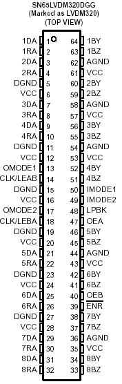
SN65LVDM320: Features: ` 8-Bit Bidirectional Data Storage Register With Full Parallel Access` Parallel Transfer Rates† Buffer Mode: Up to 475 Megatransfers Flip-Flop Mode: Up to 300 Megatransfers Latch ...
SeekIC Buyer Protection PLUS - newly updated for 2013!
268 Transactions
All payment methods are secure and covered by SeekIC Buyer Protection PLUS.

The SN65LVDM320 is an 8-bit data storage register with differential line drivers and receivers that are electrically compatible with ANSI EIA/TIA-644 for multipoint architectures with standard-compliant parallel transfer rates of 475 Mbps. The SN65LVDM320 includes transmitter and receiver data registers that remain active regardless of the state of their associated outputs.
The logic element for data flow in each direction SN65LVDM320 is configured by mode-control inputs. IMODE1 and IMODE2 control data flow in the B-to-A (bus side to digital side) direction when configured as a buffer, a D-type flip-flop, or a D-type latch. OMODE1 and OMODE2 control data flow in each of the operating modes for the A-to-B (digital side to bus side) direction. When configured in buffer mode, input data appears at the output port. In the flip-flop mode, data of SN65LVDM320 is stored on the rising edge of the appropriate clock input, CLKAB/LEAB or CLKBA/LEBA. In the latch mode, this clock pin of SN65LVDM320 also serves as an active-high transparent latch enable.
Data flow is further controlled by the A-side loopback (LPBK) input. When LPBK is high, DA input data of SN65LVDM320 is looped back to the RA output. B-side bus data is looped back to the bus in latch mode by means of the IMODE and OMODE logic states.
The A-side output enable/disable control of SN65LVDM320 is provided by OEA. When OEA is low or VCC is less than 2 V, the A side is in the high-impedance state. When OEA is high, the A side is active (high or low logic levels). The B-side output enable/disable control is provided by OEB. When OEB is low or VCC is less than 2 V, the B side is in the high impedance state. When OEB is high, the B side is active (high or low logic levels).
The A-to-B and B-to-A logic elements SN65LVDM320 are active regardless of the state of their associated outputs. New data can be entered (in latch and flip-flop modes) or previously stored data can be retained while the associated outputs are in the high-impedance or inactive states. The SN65LVDM320 also includes internally isolated analog (B-side) and digital (A-side) grounds for enhanced operation.
The SN65LVDM320 is characterized for operation from 40°C to 85°C.