Features: *A Member of the MuxIt™
Serializer-Deserializer Building-Block Chip Family
*Supports Serialization of up to 10 Bits of
Parallel Data Input at Rates up to 200 Mbps
*PLL Lock/Valid Input Provided to Enable
Link Data Transfers
*Cascadable With Additional SN65LVDS151
MuxIt Serializer-Transmitters for Wider
Parallel Input Data Channel Widths
*LVDS Compatible Differential Inputs and
Outputs Meet or Exceed the Requirements
of ANSI TIA/EIA-644-A
*LVDS Inputs and Outputs ESD Protection
Exceeds 12 kV HBM
*LVTTL Compatible Inputs for Lock/Valid,
Enables, and Parallel Data Inputs Are 5-V
Tolerant
*Operates With 3.3 V Supply
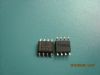
*Packaged in 32-Pin DA Thin Shrink
Small-Outline Package With 26 Mil Terminal PitchApplicationAudio
Automotive
Broadband
Digital Control
Military
Optical Networking
Security
Telephony
Video & Imaging
WirelessPinout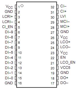 SpecificationsSupply voltage range, VCC (see Note 1) . . . . . . . . . . . . . -0.5 V to 4V
Voltage range:DI-C0 through DI-C9 input . . . . -0.5 V to VCC5 +0.5V
EN, CI_EN, LCO_EN, LVI inputs, VCC5. . -0.5 V to 5.5V
CI±, LCRI±, or MCI± Inputs, DO±, or LCO± outputs. . . . -0.5 to 4V
Electrostatic discharge, human body model (see Note 2):
MCI±, LCRI±, CI±, DO±, LCO±, and GND. . . . ±12KV
All pins. .. . . . . . . . . . . . . . . . . . . . . . . . . . . . . . ±2 kV
Charged-device model (see Note 3): All pins . . .±500 V
Continuous power dissipation. . . . . . . . .See Dissipation Rating Table
Storage temperature range. . . . . . . . . . . . . . . . . . . . .-65 to 150
Lead temperature 1,6 mm (1/16 inch) from case for 10 seconds.260Description MuxIt SN65LVDS151 is a family of general-purpose, multiple-chip building blocks for implementing parallel data serializers and deserializers. The system allows for wide parallel data to be transmitted through a reduced number of transmission lines over distances greater than can be achieved with a single-ended (e.g., LVTTL or LVCMOS) data interface. The number of bits multiplexed per transmission line is user-selectable and SN65LVDS151 allows for higher transmission efficiencies than with existing fixed ratio solutions. MuxIt utilizes the LVDS (TIA/EIA-644-A) low voltage differential signaling technology for communications between the data source and data destination.
The MuxIt family initially includes three devices supporting simplex communications: the SN65LVDS150 phase locked loop frequency multiplier, the SN65LVDS151 serializer-transmitter, and the SN65LVDS152 receiver-deserializer.
The SN65LVDS151 consists of a 10-bit parallel-in/serial-out shift register, three LVDS differential transmission line receivers, a pair of LVDS differential transmission line drivers, plus associated input buffers. It accepts up to 10 bits of user data on parallel data inputs (DI-C0 DI-C9) and serializes (multiplexes) the data for transmissio over an LVDS transmission line link. Two or more SN65LVDS151 units may be connected in series (cascaded) to accommodate wider parallel data paths for higher serialization values. Data is transmitted over the LVDS serial link at M times the input parallel data clock frequency. The multiplexing ratio M, or number of bits per data clock cycle, is programmed on the companion SN65LVDS150 MuxIt programmable PLL frequency multiplier with configuration pins (M1 M5). The range of multiplexing ratio M supported by the SN65LVDS150 MuxIt programmable PLL frequency multiplier is between 4 and 40. Table 1 shows some of the combinations of LCRI and MCI supported by the SN65LVDS150 MuxIt programmable PLL frequency multiplier.
Data is parallel loaded into the SN65LVDS151 input latches on the first rising edge of the M-clock input (MCI) signal following a rising edge of the link clock reference input (LCRI). The data is read out serially from the SN65LVDS151 shift registers on the rising edges of the M-clock input (MCI). The lowest order bit of parallel input data, DI-0, is output from DO on the third rising edge of MCI following the rising edge of LCRI. The remainin bits of parallel input data, DI-1 DI-(M-1) are clocked out sequentially, in ascending order, by subsequent MCI rising edges. The link clock output (LCO) signal rising edge is synchronized to the data output (DO) by an internal circuit clocked by MCI. The LCO signal rising edge follows the first rising edge of MCI after the rising edge of LCRI. Examples of operating waveforms for values of M = 4 and M = 10 are provided in Figure 1.
Both the LCRI and MCI signals are intended to be sourced from the SN65LVDS150 MuxIt programmable frequency multiplier. They are carried over LVDS differential connections to minimize skew and jitter. The SN65LVDS151 includes LVDS differential line drivers for both the serialized data output (DO) stream and the link clock output (LCO). The cascade input (CI) is also an LVDS connection, and when it is used it is tied to the DO output of the preceding SN65LVDS151.
An internal power-on reset (POR) and an enable input (EN) control the operation of the SN65LVDS151. When VCC is below 1.5 V, or when EN is low, the device is in a low-power disabled state, and the DO and LCO differential outputs are in a high-impedance state. When VCC is above 3 V and EN is high, the device and the two differential outputs are enabled and operating to specifications. The link clock output enable input (LCO_EN) is used to turn off the LCO output when SN65LVDS151 is not being used. Cascade input enable (CI_EN) is used to turn off the CI input when it is not being used.
Serialized data bits of SN65LVDS151 are output from the DO output, starting in ascending order, from parallel input bit DI-C0. The umber of serialized data bits output per data clock cycle is determined by the multiplexing ratio M. For values f M less than or equal to 10, the cascade input (CI±) is not used, and only the first M parallel input bits (DI-C ought DI-C[M 1])are used. For values of M greater than 10, all ten parallel input bits (DI-C0 though DI-C9) used, and the cascade input is used to shift in the remaining data bits from additional SN65LVDS151 serializers. Table 2 shows which input data bits are used as a function of the multiplier M.

 SN65LVDS151 Data Sheet