Features: Members of the Texas Instruments WidebusE Family
State-of-the-Art EPIC-II BE BiCMOS Design Significantly Reduces Power Dissipation
Latch-Up Performance Exceeds 500 mA Per JEDEC Standard JESD-17
Typical VOLP (Output Ground Bounce) < 1 V at VCC = 5 V, TA = 25°C
Distributed VCC and GND Pin Configuration Minimizes High-Speed Switching Noise
Flow-Through Architecture Optimizes PCB Layout
High-Drive Outputs (32-mA IOH, 64-mA IOL)
Package Options Include Plastic 300-mil Shrink Small-Outline (DL) and Thin Shrink Small-Outline (DGG) Packages and 380-mil Fine-Pitch Ceramic Flat (WD) Package Using 25-mil Center-to-Center Spacings
ApplicationAudio
Automotive
Broadband
Digital Control
Military
Optical Networking
Security
Telephony
Video & Imaging
WirelessPinout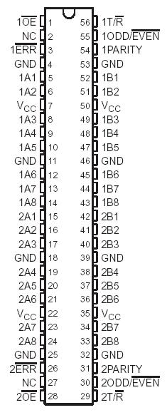 SpecificationsSupply voltage range, VCC . . . . . . . . . . . . . . . . . . . . . . . . . . . . . . . . . . . . .0.5 V to 7 V
Input voltage range, VI (except I/O ports) (see Note 1) . . . . . . . . . . . . . . .0.5 V to 7 V
Voltage range applied to any output in the high or power-off state, VO .. 0.5 V to 5.5 V
Current into any output in the low state, IO:SN54ABT16657 . . . . . . . . . . . . . . .96 mA
SN74ABT16657 . . . . . . . . . .. . . . . . .128 mA
Input clamp current, IIK (VI < 0) . . . . . . . . . . . . . . . . . . . . . . . . . . . . . . . . . . . . .. .18 mA
Output clamp current, IOK (VO < 0) . . . . . . . . . . . . . . . . . . . . . . . . . . . . . . . . . . . . 50 mA
Package thermal impedance, qJA (see Note 2): DGG package . . . . . . . . . . . . . . ..81°C/W
DL package . . . . . . . . . . . . . . . . ..74°C/W
Storage temperature range, Tstg . . . . . . . . . . . . . . . . . . . . . . . . . . . . . .. .65°C to 150°CDescription The 'ABT16657 contain two noninverting octal transceiver sections with separate parity generator/checker circuits and control signals. For either section, the transmit/receive (1T/R or 2T/R ) input determines the direction of data flow.When 1T/R (or 2T/R ) is high, data flows from the 1A (or 2A) port to the 1B (or 2B) port (transmit mode); when 1T/R (or 2T/R ) is low, data flows from the 1B (or 2B) port to the 1A (or 2A) port (receive mode). When the output-enable (1OE or 2OE ) input is high, both the 1A (or 2A) and 1B (or 2B) ports are in the high-impedance state.
Odd or even parity is selected by a logic high or low level, respectively, on the 1ODD/EVEN (or 2ODD/EVEN ) input. 1PARITY (or 2PARITY) carries the parity bit value; 'ABT16657 is an output from the parity generator/checker in the transmit mode and an input to the parity generator/checker in the receive mode. In the transmit mode, after the 1A (or 2A) bus is polled to determine the number of high bits, 1PARITY (or 2PARITY) is set to the logic level that maintains the parity sense selected by the level at the 1ODD/EVEN (or 2ODD/EVEN ) input. For example, if 1ODD/EVEN is low (even parity selected) and there are five high bits on the 1A bus, then 1PARITY is set to the logic high level so that an even number of the nine total bits (eight 1A-bus bits plus parity bit) are high.
In the receive mode of 'ABT16657 , after the 1B (or 2B) bus is polled to determine the number of high bits, the 1ERR (or 2ERR ) output logic level indicates whether or not the data to be received exhibits the correct parity sense. For example, if 1ODD/EVEN is high (odd parity selected), 1PARITY is high, and there are three high bits on the 1B bus, then 1ERR is low, indicating a parity error.
To ensure the high-impedance state of 'ABT16657 during power up or power down, OOE should be tied to V
CC through a pullup resistor; the minimum value of the resistor is determined by the current-sinking capability of the driver.The SN54ABT16657 is characterized for operation over the full military temperature range of 55°C to 125°C. The SN74ABT16657 is characterized for operation from 40°C to 85°C.

 SN74ABT16657 Data Sheet


