SN74ALVCH16836

Features: · Member of the Texas Instruments WidebusE Family· EPIC E (Enhanced-Performance Implanted CMOS) Submicron Process· Designed to Comply With JEDEC 168-Pin and 200-Pin SDRAM Buffered DIMM Specification· Bus Hold on Data Inputs Eliminates the Need for External Pullup/Pulldown Resistors· Pack...

product image

SN74ALVCH16836 Picture
SeekIC No. : 004498306 Detail

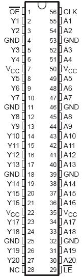
SN74ALVCH16836: Features: · Member of the Texas Instruments WidebusE Family· EPIC E (Enhanced-Performance Implanted CMOS) Submicron Process· Designed to Comply With JEDEC 168-Pin and 200-Pin SDRAM Buffered DIMM Spe...

floor Price/Ceiling Price

Part Number:
SN74ALVCH16836
Supply Ability:
5000

Price Break

  • Qty
  • 1~5000
  • Unit Price
  • Negotiable
  • Processing time
  • 15 Days
Total Cost: $ 0.00

SeekIC Buyer Protection PLUS - newly updated for 2013!

  • Escrow Protection.
  • Guaranteed refunds.
  • Secure payments.
  • Learn more >>

Month Sales

268 Transactions

Rating

evaluate  (4.8 stars)

Upload time: 2025/12/24

Payment Methods

All payment methods are secure and covered by SeekIC Buyer Protection PLUS.

Notice: When you place an order, your payment is made to SeekIC and not to your seller. SeekIC only pays the seller after confirming you have received your order. We will also never share your payment details with your seller.
Product Details

Description


Features:

· Member of the Texas Instruments
  WidebusE Family
· EPIC E (Enhanced-Performance Implanted
  CMOS) Submicron Process
· Designed to Comply With JEDEC 168-Pin
  and 200-Pin SDRAM Buffered DIMM Specification
· Bus Hold on Data Inputs Eliminates the
  Need for External Pullup/Pulldown Resistors
· Package Options Include Plastic Shrink
  Small-Outline (DL) and Thin Shrink
  Small-Outline (DGG) Packages


Pinout

  Connection Diagram


Specifications

Supply voltage range, VCC . . . . . . . . . . . . . . . . . . . . . . . . . . . . . . . . . . . . . . . . . . . . . . . . . 0.5 V to 4.6 V
Input voltage range, VI (see Note 1) . . . . . . . . . . . . . . . . . . . . . . . . . . . . . . . . . . . . . . . . . .0.5 V to 4.6 V
Output voltage range, VO (see Notes 1 and 2) . . . . . . . . . . . . . . . . . . . . . . . . . . . .  0.5 V to VCC + 0.5 V
Input clamp current, IIK (VI < 0) . . . . . . . . . . . . . . . . . . . . . . . . . . . . . . . . . . . . . . . . . . . . . . . . . . . .50 mA
Output clamp current, IOK (VO < 0) . . . . . . . . . . . . . . . . . . . . . . . . . . . . . . . . . . . . . . . . . . . . . . . . . 50 mA
Continuous output current, IO . . . . . . . . . . . . . . . . . . . . . . . . . . . . . . . . . . . . . . . . . . . . . . . . . . . . . ±50 mA
Continuous current through each VCC or GND . . . . . . . . . . . . . . . . . . . . . . . . . . . . . . . . . . . . . . . . ±100 mA
Package thermal impedance, qJA (see Note 3): DGG package . . . . . . . . . . . . . . . . . . . . . . . . . . . . . 81°C/W
DL package . . . . . . . . . . . . . . . . . . . . . . . . . . . . . . . . . .  . . . . . . . . . . . . . . . . . . . . . . . . . . . . . . . . . .74°C/W
Storage temperature range, Tstg . . . . . . . . . . . . . . . . . . . . . . . . . . . . . . . . . . . . . . . . . . . .  65°C to 150°C
† Stresses beyond those listed under "absolute maximum ratings" may cause permanent damage to the device. These are stress ratings only, and
functional operation of the device at these or any other conditions beyond those indicated under "recommended operating conditions" is not
implied. Exposure to absolute-maximum-rated conditions for extended periods may affect device reliability.
NOTES: 1. The input negative-voltage and output voltage ratings may be exceeded if the input and output current ratings are observed.
2. This value is limited to 4.6 V maximum.
3. The package thermal impedance is calculated in accordance with JESD 51.


Description

This SN74ALVCH16836 20-bit universal bus driver is designed for 1.65-V to 3.6-V VCC operation.

Data of SN74ALVCH16836 flow from A to Y is controlled by the output-enable (OE) input. The device operates in the transparent mode when the latch-enable (LE) input is low. The A data is latched if the clock (CLK) input is held at a high or low logic level. If LE is high, the A data is stored in the latch/flip-flop on the low-to-high transition of CLK. When OE is high, the outputs are in the high-impedance state. To ensure the high-impedance state during power up or power down, OE should be tied to VCC through a pullup resistor; the minimum value of the resistor is determined by the current-sinking capability of the driver.

Active bus-hold circuitry is provided to hold unused or floating data inputs at a valid logic level. The SN74ALVCH16836 is characterized for operation from 40°C to 85°C.


Customers Who Bought This Item Also Bought

Margin,quality,low-cost products with low minimum orders. Secure your online payments with SeekIC Buyer Protection.
Cable Assemblies
Potentiometers, Variable Resistors
Integrated Circuits (ICs)
Sensors, Transducers
Audio Products
View more