Features: ` Member of the Texas Instruments Widebus™ Family
` TI-OPC™ Circuitry Limits Ringing on Unevenly Loaded Backplanes
` OEC™ Circuitry Improves Signal Integrity and Reduces Electromagnetic Interference
` Bidirectional Interface Between GTLP Signal Levels and LVTTL Logic Levels
` LVTTL Interfaces Are 5-V Tolerant
` High-Drive GTLP Outputs (100 mA)
` LVTTL Outputs (24 mA/24 mA)
` Variable Edge-Rate Control (ERC
) Input Selects GTLP Rise and Fall Times for Optimal Data-Transfer Rate and Signal Integrity in Distributed Loads
` Ioff, Power-Up 3-State, and BIAS VCC Support Live Insertion
` Bus Hold on A-Port Data Inputs
` Distributed VCC and GND Pins Minimize High-Speed Switching Noise
` Latch-Up Performance Exceeds 100 mA Per JESD 78, Class IIPinout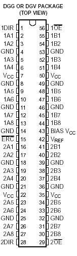 Specifications
| |
|
|
MIN |
MAX |
UNIT |
VCC
BIAS VCC |
Supply voltage range |
|
0.5 |
4.6 |
V |
VI
|
Input voltage range(2) |
A-port, ERC , and control inputs |
0.5 |
7 |
V |
| B port and VREF |
0.5 |
4.6 |
| VO |
Voltage range applied to any output in the
high-impedance or power-off state(2)
|
A port |
0.5 |
7 |
V |
| B port |
0.5 |
4.6 |
IO
|
Current into any output in the low state |
A port |
|
48 |
mA |
| B port |
|
200 |
| IO |
Current into any A-port output in the high state(3) |
|
|
48 |
mA |
| |
Continuous current through each VCC or GND |
|
|
±100 |
mA |
| IIK |
Input clamp current |
VI < 0 |
|
50 |
mA |
| IOK |
Output clamp current |
VO < 0 |
|
50 |
mA |
qJA
|
Package thermal impedance(4) |
DGG package |
|
64 |
°C/W |
| DGV package |
|
48 |
| GQL package |
|
42 |
| Tstg |
Storage temperature range |
|
65 |
150 |
°C |
Description The SN74GTLPH1645 is a high-drive, 16-bit bus transceiver that provides LVTTL-to-GTLP and GTLP-to-LVTTL signal-level translation. It is partitioned as two 8-bit transceivers. The device provides a high-speed interface between cards operating at LVTTL logic levels and a backplane operating at GTLP signal levels. High-speed (about three times faster than standard LVTTL or TTL) backplane operation is a direct result of GTLP's reduced output swing (<1 V), reduced input threshold levels, improved differential input, OEC™ circuitry, and TI-OPC™ circuitry. Improved GTLP OEC and TI-OPC circuits minimize bus-settling time and have been designed and tested using several backplane models. The high drive allows incident-wave switching in heavily loaded backplanes with equivalent load impedance down to 11 W.
GTLP is the Texas Instruments derivative of the Gunning Transceiver Logic (GTL) JEDEC standard JESD 8-3. The ac specification of the SN74GTLPH1645 is given only at the preferred higher noise-margin GTLP, but the user has the flexibility of using this SN74GTLPH1645 device at either GTL (V
TT = 1.2 V and V
REF = 0.8 V) or GTLP (V
TT = 1.5 V and V
REF = 1 V) signal levels.
Normally, the SN74GTLPH1645 B port operates at GTLP signal levels. The A-port and control inputs operate at LVTTL logic levels, but are 5-V tolerant and are compatible with TTL and 5-V CMOS inputs. V
REF is the B-port differential input reference voltage.
This SN74GTLPH1645 device is fully specified for live-insertion applications using I
off, power-up 3-state, and BIAS V
CC. The Ioff circuitry disables the outputs, preventing damaging current backflow through the device when it is powered down. The power-up 3-state circuitry places the outputs in the high-impedance state during power up and power down, which prevents driver conflict. The BIAS V
CC circuitry precharges and preconditions the B-port input/output connections, preventing disturbance of active data on the backplane during card insertion or removal, and permits true live-insertion capability.
This SN74GTLPH1645 GTLP device features TI-OPC circuitry, which actively limits the overshoot caused by improperly terminated backplanes, unevenly distributed cards, or empty slots during low-to-high signal transitions. This improves signal integrity, which allows adequate noise margin to be maintained at higher frequencies.
SN74GTLPH1645 High-drive GTLP backplane interface devices feature adjustable edge-rate control (ERC ). Changing the ERC input voltage between GND and V
CC adjusts the B-port output rise and fall times. This allows the designer to optimize system data-transfer rate and signal integrity to the backplane load.
Active bus-hold circuitry holds unused or undriven LVTTL data inputs at a valid logic state. Use of pullup or pulldown resistors with the bus-hold circuitry is not recommended.
When V
CC SN74GTLPH1645 is between 0 and 1.5 V, the device is in the high-impedance state during power up or power down. However, to ensure the high-impedance state above 1.5 V, the output-enable (OE ) input should be tied to V
CC through a pullup resistor; the minimum value of the resistor is determined by the current-sinking capability of the driver.

 SN74GTLPH1645 Data Sheet


