Features: · Look-Ahead Circuitry Enhances Cascaded Counters
· Fully Synchronous in Count Modes
· Parallel Asynchronous Load for Modulo-N Count Lengths
· Asynchronous Clear
· Package Options Include Plastic Small-Outline (D) and Ceramic Flat (W) Packages, Ceramic Chip Carriers (FK), and Standard Plastic (N) and Ceramic (J) 300-mil DIPs
Pinout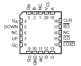 Specifications
Supply voltage range, VCC . . . . . . . . . . . . . . . . . . . . . . . . . . . . . . . . . . . . . . . . . . . . . . . 0.5 V to 7 V
Input clamp current, IIK (VI < 0 or VI > VCC) (see Note 1) . . . . . . . . . . . .. . . . . . . . . . . . . . . . ±20 mA
Output clamp current, IOK (VO < 0 or VO > VCC) (see Note 1) . . . . . . . . . . . . . . . . . . . . . . . . ±20 mA
Continuous output current, IO (VO = 0 to VCC) . . . . . . . . . . . . . . . . . . . . . . . . . . . . . . . . . . . . ±25 mA
Continuous current through VCC or GND . . . . . . . . . . . . . . . . . . . . . . . . . . . . . . . . . . . . .. . . . ±50 mA
Package thermal impedance, JA (see Note 2): D package . . . . . . . . . . . . . . . . . . . . . . . . . . 113°C/W
N package . . . . . . . . . . . . . . . . . . . . . . . . . . . 78°C/W
Storage temperature range, Tstg . . . . . . . . . . . . . . . . . . . . . . . . . . . . . . . . .. . . . . . . 65°C to 150°C
† Stresses beyond those listed under "absolute maximum ratings" may cause permanent damage to the device. These are stress ratings only, and functional operation of the device at these or any other conditions beyond those indicated under "recommended operating conditions" is not implied. Exposure to absolute-maximum-rated conditions for extended periods may affect device reliability.
NOTES: 1. The input and output voltage ratings may be exceeded if the input and output current ratings are observed.
2. The package thermal impedance is calculated in accordance with JESD 51, except for through-hole packages, which use a trace length of zero.
DescriptionThe 'HC193 are 4-bit synchronous, reversible, up/down binary counters. Synchronous operation is provided by having all flip-flops clocked
simultaneously so that the outputs change coincidentally with each other when so instructed by the steering logic. This mode of operation eliminates the output counting spikes normally associated with asynchronous (ripple-clock) counters.
The SN74HC193 outputs of the four flip-flops are triggered on a low-to-high-level transition of either count (clock) input (UP or DOWN). The direction of counting is determined by which count input is pulsed while the other count input is high.
All four counters are fully programmable; that is, each output may be preset to either level by placing a low on the load (LOAD) input and entering the desired data at the data inputs. The SN74HC193 output changes to agree with the data inputs independently of the count pulses. This feature allows the counters to be used as modulo-N dividers by simply modifying the count length with the preset inputs.
A SN74HC193 clear (CLR) input has been provided that forces all outputs to the low level when a high level is applied. The clear function is independent of the count and LOAD inputs.
These SN74HC193 counters were designed to be cascaded without the need for external circuitry. The borrow (BO) output produces a low-level pulse while the count is zero (all outputs low) and DOWN is low. Similarly, the carry (CO) output produces a low-level pulse while the count is maximum (9 or 15) and UP is low. The counters can then be easily cascaded by feeding BO and CO to DOWN and UP, respectively, of the succeeding counter.
The SN54HC193 is characterized for operation over the full military temperature range of 55°C to 125°C. The SN74HC193 is characterized for operation from 40°C to 85°C.

 SN74HC193 Data Sheet


