Product
: AND
Maximum Operating Temperature
: + 125 C
Mounting Style
: SMD/SMT
Packaging
: Reel
Package / Case
: TSSOP-14
Supply Voltage - Min
: 2 V
Logic Family
: 74HC
Number of Gates
: Dual
Supply Voltage - Max
: 6 V
High Level Output Current
: - 5.2 mA
Low Level Output Current
: 5.2 mA
Number of Lines (Input / Output)
: 4 / 1
Propagation Delay Time
: 110 ns
Features: `Qualification in Accordance With AEC-Q100†
`Qualified for Automotive Applications
` Customer-Specific Configuration Control Can Be Supported Along With Major-Change Approval
` Wide Operating Voltage Range of 2 V to 6 V
` Outputs Can Drive up to Ten LSTTL Loads
` Low Power Consumption, 20-A Max ICC
` Typical tpd = 11 ns
`±4-mA Output Drive at 5 V
` Low Input Current of 1 A Max
† Contact factory for details. Q100 qualification data available on request.
Pinout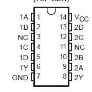 Specifications
Supply voltage range, VCC . . . . . . . . . . . . . . . . . . . . . . . . . . . . . . . . . . . . . . . . −0.5 V to 7 V
Input clamp current, IIK (VI < 0 or VI > VCC) (see Note 1) . . . . . . . . . . . . . . . . . .. . ±20 mA
Output clamp current, IOK (VO < 0 or VO > VCC) (see Note 1) . . . . . . . . . . . . . .. . . ±20 mA
Continuous output current, IO (VO = 0 to VCC) . . . . . . . . . . . . . . . . . . . . . . . . . . . . ±25 mA
Continuous current through VCC or GND . . . . . . . . . . . . . . . . . . . . . . . . . . . . . . . . . ±50 mA
Package thermal impedance, JA (see Note 2): D package . . . . . . . . . . . . . . . . . . 86°C/W
PW package . . . . . . . . . . . . . . . . 113°C/W
Storage temperature range, Tstg . . . . . . . . . . . . . . . . . . . . . . . . . . . . . . . −65°C to 150°C
† Stresses beyond those listed under "absolute maximum ratings" may cause permanent damage to the device. These are stress ratings only, and functional operation of the device at these or any other conditions beyond those indicated under "recommended operating conditions" is not implied. Exposure to absolute-maximum-rated conditions for extended periods may affect device reliability.
NOTES: 1. The input and output voltage ratings may be exceeded if the input and output current ratings are observed.
2. The package thermal impedance is calculated in accordance with JESD 51-7.
DescriptionThis SN74HC21QPWRQ1 device contains two independent 4-input AND gates. SN74HC21QPWRQ1 performs the Boolean function Y = A • B • C • D or Y = A+B+C+D in positive logic.
Parameters: | Technical/Catalog Information | SN74HC21QPWRQ1 |
| Vendor | Texas Instruments (VA) |
| Category | Integrated Circuits (ICs) |
| Number of Circuits | 2 - Dual |
| Package / Case | 14-TSSOP |
| Logic Type | AND Gate |
| Packaging | Digi-Reel? |
| Mounting Type | Surface Mount |
| Number of Inputs | 4 |
| Current - Output High, Low | 4mA, 4mA |
| Supply Voltage | 2 V ~ 6 V |
| Operating Temperature | -40°C ~ 85°C |
| Voltage - Supply | 2 V ~ 6 V |
| Drawing Number | 296; 4040064; PW; 8, 14, 16, 20, 24, 28 |
| Lead Free Status | Lead Free |
| RoHS Status | RoHS Compliant |
| Other Names | SN74HC21QPWRQ1
SN74HC21QPWRQ1
296 18317 6 ND
296183176ND
296-18317-6
|

 SN74HC21QPWRQ1 Data Sheet


