Features: 2-V to 5.5-V VCC Operation
Max tpd of 11 ns at 5 V
Support Mixed-Mode Voltage Operation on
All Ports
Schmitt-Trigger Circuitry on A, B, and CLR
Inputs for Slow Input Transition Rates
Overriding Clear Terminates Output Pulse
Glitch-Free Power-Up Reset on OutputsPinout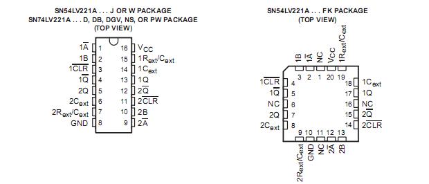 SpecificationsSupply voltage range, VCC −0.5 V to 7 V . . . . . . . . . . . . . . . . . . . . . . . . . . . . . . . . . . . . . . . . . . . . . . . . . . . . . . . . . .
Input voltage range, VI (see Note 1) −0.5 V to 7 V . . . . . . . . . . . . . . . . . . . . . . . . . . . . . . . . . . . . . . . . . . . . . . . . . .
Output voltage range in high or low state, VO (see Notes 1 and 2) −0.5 V to VCC + 0.5 V . . . . . . . . . . . . . . . . .
Output voltage range in power-off state, VO (see Note 1) −0.5 V to 7 V . . . . . . . . . . . . . . . . . . . . . . . . . . . . . . . .
Input clamp current, IIK (VI < 0) −20 mA . . . . . . . . . . . . . . . . . . . . . . . . . . . . . . . . . . . . . . . . . . . . . . . . . . . . . . . . . . .
Output clamp current, IOK (VO < 0) −50 mA . . . . . . . . . . . . . . . . . . . . . . . . . . . . . . . . . . . . . . . . . . . . . . . . . . . . . . . .
Continuous output current, IO (VO = 0 to VCC) ±25 mA . . . . . . . . . . . . . . . . . . . . . . . . . . . . . . . . . . . . . . . . . . . . . .
Continuous current through VCC or GND ±50 mA . . . . . . . . . . . . . . . . . . . . . . . . . . . . . . . . . . . . . . . . . . . . . . . . . . .
Package thermal impedance, JA (see Note 3): D package 73°C/W . . . . . . . . . . . . . . . . . . . . . . . . . . . . . . . . . . .
DB package 82°C/W . . . . . . . . . . . . . . . . . . . . . . . . . . . . . . . . .
DGV package 120°C/W . . . . . . . . . . . . . . . . . . . . . . . . . . . . . . .
NS package 64°C/W . . . . . . . . . . . . . . . . . . . . . . . . . . . . . . . . .
PW package 108°C/W . . . . . . . . . . . . . . . . . . . . . . . . . . . . . . . .
Storage temperature range, Tstg −65°C to 150°C . . . . . . . . . . . . . . . . . . . . . . . . . . . . . . . . . . . . . . . . . . . . . . . . . . . DescriptionThe 'LV221A devices are dual multivibrators designed for 2-V to 5.5-V VCC operation. Each multivibrator has
a negative-transition-triggered (A) input and a positive-transition-triggered (B) input, either of which can be used
as an inhibit input.
These edge-triggered multivibrators LV221A feature output pulse-duration control by three methods. In the first method,
the A input is low and the B input goes high. In the second method, the B input is high and the A input goes low.
In the third method, the A input is low, the B input is high, and the clear (CLR) input goes high.
The output pulse duration is programmable by selecting external resistance and capacitance values. The
external timing capacitor must be connected between Cext and Rext/Cext(positive) and an external resistor
connected between Rext/Cext and VCC. To obtain variable pulse durations, connect an external variable resistor
between Rext/Cext and VCC. The output pulse duration also can be reduced by taking CLR low.
Pulse triggering occurs at a particular voltage level and is not related directly to the transition time of the input
pulse. The A, B, and CLR inputs have Schmitt triggers with sufficient hysteresis to handle slow input transition
rates with jitter-free triggering at the outputs.
Once triggered, the LV221A outputs are independent of further transitions of the A and B inputs and are a function of
the timing components, or the output pulses can be terminated by the overriding clear. Input pulses can be of
any duration relative to the output pulse. Output pulse duration can be varied by choosing the appropriate timing
components. Output rise and fall times are TTL compatible and independent of pulse duration. Typical triggering
and clearing sequences are illustrated in the input/output timing diagram.
The LV221A variance in output pulse duration from device to device typically is less than ±0.5% for given external timing
components. An example of this distribution for the 'LV221A is shown in Figure 8. Variations in output pulse
duration versus supply voltage and temperature are shown in Figure 5.
During power up, Q outputs are in the low state, and Q outputs are in the high state. The outputs are glitch free,
without applying a reset pulse.
These devices LV221A are fully specified for partial-power-down applications using Ioff. The Ioff circuitry disables the
outputs, preventing damaging current backflow through the devices when they are powered down.
Pin assignments are identical to those of the 'AHC123A and 'AHCT123A devices, so the 'LV221A can be
substituted for those devices not using the retrigger feature.

 SN74LV221A Data Sheet


