SN74LVC2G06-Q1

Features: Qualification in Accordance With AEC-Q100†Qualified for Automotive ApplicationsCustomer-Specific Configuration Control Can Be Supported Along With Major-Change ApprovalSupports 5-V VCC OperationMax tpd of 3.4 ns at 3.3 VLow Power Consumption, 10-µA Max ICC±24-mA Output Drive ...

product image

SN74LVC2G06-Q1 Picture
SeekIC No. : 004499300 Detail

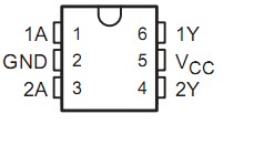
SN74LVC2G06-Q1: Features: Qualification in Accordance With AEC-Q100†Qualified for Automotive ApplicationsCustomer-Specific Configuration Control Can Be Supported Along With Major-Change ApprovalSupports 5-V V...

floor Price/Ceiling Price

Part Number:
SN74LVC2G06-Q1
Supply Ability:
5000

Price Break

  • Qty
  • 1~5000
  • Unit Price
  • Negotiable
  • Processing time
  • 15 Days
Total Cost: $ 0.00

SeekIC Buyer Protection PLUS - newly updated for 2013!

  • Escrow Protection.
  • Guaranteed refunds.
  • Secure payments.
  • Learn more >>

Month Sales

268 Transactions

Rating

evaluate  (4.8 stars)

Upload time: 2025/12/24

Payment Methods

All payment methods are secure and covered by SeekIC Buyer Protection PLUS.

Notice: When you place an order, your payment is made to SeekIC and not to your seller. SeekIC only pays the seller after confirming you have received your order. We will also never share your payment details with your seller.
Product Details

Description


Features:

Qualification in Accordance With AEC-Q100†
Qualified for Automotive Applications
Customer-Specific Configuration Control Can Be Supported Along With Major-Change Approval
Supports 5-V VCC Operation
Max tpd of 3.4 ns at 3.3 V
Low Power Consumption, 10-µA Max ICC
±24-mA Output Drive at 3.3 V
Typical VOLP (Output Ground Bounce) <0.8 V at VCC = 3.3 V, TA = 25°C
Typical VOHV (Output VOH Undershoot) >2 V at VCC = 3.3 V, TA = 25°C
Inputs and Open-Drain Outputs Accept Voltages Up To 5.5 V
Ioff Supports Partial-Power-Down Mode Operation
Latch-Up Performance Exceeds 100 mA Per JESD 78, Class II
ESD Protection Exceeds JESD 22
   −  2000-V Human-Body Model (A114-A)
   −  200-V Machine Model (A115-A)
   −  1000-V Charged-Device Model (C101)


Pinout

  Connection Diagram


Specifications

Supply voltage range, VCC   . . . . . . . . . . . . . . . . . . . . . . . . . . . . . . .−0.5 V to 6.5 V
Input voltage range, VI (see Note 1)   . . . . . . . . . . . . . . . . . . . . . . .−0.5 V to 6.5 V
Voltage range applied to any output in the high-impedance or power-off state, VO
(see Note 1)  . . . . . . . . . . . . . . . . . . . . . . . . . . . . . . . . . . . . . . .. . . .−0.5 V to 6.5 V
Voltage range applied to any output in the high or low state, VO
(see Notes 1 and 2)   . . . . . . . . . . . . . . . . . . . . . . . . . . . . . . . . . . . .−0.5 V to 6.5 V
Input clamp current, IIK (VI < 0)   . . . . . . . . . . . . . . . . . . . . . . . . . . . . . . . . .−50 mA
Output clamp current, IOK (VO < 0)   . . . . . . . . . . . . . . . . . . . . . . . . . .  . . . .−50 mA
Continuous output current, IO  . . . . . . . . . . . . . . . . . . . . . . . . . . . . . . . . . . .±50 mA
Continuous current through VCC or GND  . . . . . . . . . . . . . . . . . . . . . . . . . .±100 mA
Package thermal impedance, JA (see Note 3): DBV package   . . . . . . .. . .165°C/W
                                         DCK package   . . . . . . . . . . . . . . . . . . . . . . . . . .259°C/W
Storage temperature range, Tstg  . . . . . . . . . . . . . . . . . . .  . . . . . . −65°C to 150°C
† Stresses beyond those listed under "absolute maximum ratings" may cause permanent damage to the device. These are stress ratings only, and functional operation of the device at these or any other conditions beyond those indicated under "recommended operating conditions" is not implied. Exposure to absolute-maximum-rated conditions for extended periods may affect device reliability.
NOTES: 1. The input negative-voltage and output voltage ratings may be exceeded if the input and output current ratings are observed.
2. The value of VCC is provided in the recommended operating conditions table.
3. The package thermal impedance is calculated in accordance with JESD 51-7.


Description

This dual inverter buffer/driver is designed for 1.65-V to 5.5-V VCC operation.

The output of the SN74LVC2G06 device is open drain and can be connected to other open-drain outputs to implement active-low wired-OR or active-high wired-AND functions. The maximum sink current is 32 mA.

This device SN74LVC2G06-Q1 is fully specified for partial-power-down applications using Ioff. The Ioff circuitry disables the outputs, preventing damaging current backflow through the device when it is powered down.


Customers Who Bought This Item Also Bought

Margin,quality,low-cost products with low minimum orders. Secure your online payments with SeekIC Buyer Protection.
Potentiometers, Variable Resistors
Inductors, Coils, Chokes
Programmers, Development Systems
Transformers
Soldering, Desoldering, Rework Products
Power Supplies - Board Mount
View more