SN74LVCE161284

PinoutSpecificationsSupply voltage range, VCC CABLE. . . . . . . . . . . . . . . . . . . . . . . . . . . . . . . . . . . . . . . .0.5 V to7 VVCC . . . . . . . . . . . . . . . . . . . . . . . . . . . . . . . . . . . . . . . . . . . .−0.5 V to 4.6 VInput and output voltage range, VI and VO: Ca...

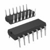
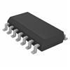
product image

SN74LVCE161284 Picture
SeekIC No. : 004499383 Detail

SN74LVCE161284: PinoutSpecificationsSupply voltage range, VCC CABLE. . . . . . . . . . . . . . . . . . . . . . . . . . . . . . . . . . . . . . . .0.5 V to7 VVCC . . . . . . . . . . . . . . . . . . . . . . . . . . ....

floor Price/Ceiling Price

Part Number:
SN74LVCE161284
Supply Ability:
5000

Price Break

  • Qty
  • 1~5000
  • Unit Price
  • Negotiable
  • Processing time
  • 15 Days
Total Cost: $ 0.00

SeekIC Buyer Protection PLUS - newly updated for 2013!

  • Escrow Protection.
  • Guaranteed refunds.
  • Secure payments.
  • Learn more >>

Month Sales

268 Transactions

Rating

evaluate  (4.8 stars)

Upload time: 2024/5/16

Payment Methods

All payment methods are secure and covered by SeekIC Buyer Protection PLUS.

Notice: When you place an order, your payment is made to SeekIC and not to your seller. SeekIC only pays the seller after confirming you have received your order. We will also never share your payment details with your seller.
Product Details

Description


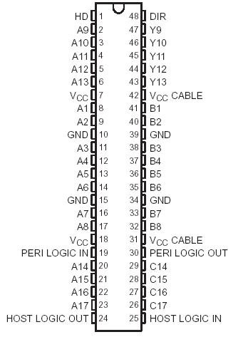
Pinout

  Connection Diagram


Specifications

Supply voltage range, VCC CABLE . . . . . . . . . . . . . . . . . . . . . . . . . . . . . . . . . . . . . . . .0.5 V to 7 V
                                   VCC . . . . . . . . . . . . . . . . . . . . . . . . . . . . . . . . . . . . . . .  . . . . . −0.5 V to 4.6 V
Input and output voltage range, VI and VO: Cable side (see Notes 1 and 2) . . . . . . . .2 V to 7 V 
                                                               Peripheral side (see Note 1)  . . . . . .−0.5 V to VCC + 0.5 V
Input clamp current, IIK (VI < 0) . . . . . . . . . . . . . . . . . . . . . . . . . . . . . . . . . . . .. . . . .. . . . . .20mA
Output clamp current, IOK (VO < 0) . . . . . . . . . . . . . . . . . . . . . . .. . . . . . . . . . . . . . . . . . . . .50 mA
Continuous output current, IO Except PERI LOGIC OUT. . . . . . . . . . . . . . . . . . . . . . . . . . . . .±50 mA 
                                               PERI LOGIC OUT . . . . . . . . . . . . . . . . . . . . . .  . . . . . . . . . . .±100 mA
Continuous current through each VCC or GND . . . . . . . . . . . . . .. . . . . . . . . . . . . . . . . . . . .±200 mA
Output high sink current, ISK (VO = 5.5 V and VCC CABLE = 3 V) . . . . . . . . . . . . .  . . . . . . . . .65 mA
Package thermal impedance, JA (see Note 3): DGG package . . . . . . . . . . . . .. . . .  . . . . . .70°C/W
                                                                          DL package . . . . . . . . . . . .. . . . . .  . . . . . . . . .63°C
Storage temperature range, Tstg . . . . . . . . . . . . . . . . . . . . . . . . . . . . . . . . . . . . . .65°C to 150°C
1. The input and output voltage ratings may be exceeded if the input and output current ratings are observed.
2. The ac input-voltage pulse duration is limited to 40 ns if the amplitude is greater than −0.5 V.
3. The package thermal impedance is calculated in accordance with JESD 51-7.


Description

The SN74LVCE161284 is designed for 3-V to 3.6-V VCC operation. This device provides asynchronous two-way communication between data buses. The control-function implementation minimizes external timing requirements.

This device has eight bidirectional bits; data can flow in the A-to-B direction when the direction-control input (DIR) is high and in the B-to-A direction when DIR is low. This device also has five drivers that drive the cable side, and four receivers. The SN74LVCE161284 has one receiver dedicated to the HOST LOGIC line and a driver to drive the PERI LOGIC line.

The SN74LVCE161284 output drive mode is determined by the high-drive (HD) control pin. When HD is high, the outputs are in a totem-pole configuration, and in an open-drain configuration when HD is low. This meets the drive requirements as specified in the IEEE Std 1284-I (level-1 type) and IEEE Std 1284-II (level-2 type) parallel peripheral-interface specifications. Except for HOST LOGIC IN and peripheral logic out (PERI LOGIC OUT), all cable-side pins have a 1.4-kΩ integrated pullup resistor. The pullup resistor is switched off if the associated output driver is in the low state or if the output voltage is above VCC CABLE. If VCC CABLE is off, PERI LOGIC OUT is set to low.

The device SN74LVCE161284 has two supply voltages. VCC is designed for 3-V to 3.6-V operation. VCC CABLE supplies the inputs and output buffers of the cable side only and is designed for 3-V to 3.6-V and for 4.7-V to 5.5-V operation. Even when VCC CABLE is 3 V to 3.6 V, the cable-side I/O pins are 5-V tolerant.

The SN74LVCE161284 Y outputs (Y9−Y13) stay in the high state after power on until an associated input (A9−A13) goes high. When an associated input goes high, all Y outputs are activated, and noninverting signals of the associated inputs are driven through Y outputs. This special feature prevents printer-system errors caused by deasserting the BUSY signal in the cable at power on.


Customers Who Bought This Item Also Bought

Margin,quality,low-cost products with low minimum orders. Secure your online payments with SeekIC Buyer Protection.
RF and RFID
Audio Products
Circuit Protection
Soldering, Desoldering, Rework Products
Crystals and Oscillators
View more