Pinout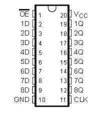 SpecificationsSupply voltage range, VCC . . . . . . . . . . . . . . . . . . . . . . . . . . . . . . . . . . . . . . . . . . . . . . . .. . 0.5 V to 4.6 V
Input voltage range, VI (see Note 1) . . . . . . . . . . . . . . . . . . . . . . . . . . . . . . . . . . . . . . . . . . . . 0.5 V to 7 V
Voltage range applied to any output in the high state or power-off state, VO (see Note 1) . . 0.5 V to 7 V
Current into any output in the low state, IO: SN54LVT574 . . . . . . . . . . . . . . . . . . . . . . . . . . . . .. . . . 96 mA
SN74LVT574 . . . . . . . . . . . . . . . . . . . . . . . . . . . . . . . . . . . . 128 mA
Current into any output in the high state, IO (see Note 2): SN54LVT574 . . . . . . . . . . . . . . . . . . . . . . 48 mA
SN74LVT574 . . . . . . . . . . . . . . . . . . . . . . . . . 64 mA
Input clamp current, IIK (VI < 0) . . . . . . . . . . . . . . . . . . . . . . . . . . . . . . . . . . . . . . . . . . . . . . . . . . . . 50 mA
Output clamp current, IOK (VO < 0) . . . . . . . . . . . . . . . . . . . . . . . . . . . . . . . . . . . . . . . . . . . . . . . . . . 50 mA
Maximum power dissipation at TA = 55°C (in still air) (see Note 3): DB package . . . . . . . . . . . . .. . . . 0.6 W
DW package . . . . . . . . . . . . . . . . . . . . . . . . . . . . . . . . . . . . . . . . . . . . . . . . . . . . 1.6 W
PW package . . . . . . . . . . . . . . . . . . . . . . . . . . . . . . . . . . . . . . . . . . . . . . . . . . . . 0.7 W
Storage temperature range, Tstg . . . . . . . . . . . . . . . . . . . . . . . . . . . . . . . . . . . . . . . . . .. . . 65°C to 150°C DescriptionThese octal flip-flops SN74LVT574 are designed specifically for low-voltage (3.3-V) VCC operation, but with the capability toprovide a TTL interface to a 5-V system environment.
The eight flip-flops of the SN74LVT574 are edge-triggered D-type flip-flops. On the positive transition of the clock(CLK) input, the Q outputs are set to the logic levels set up at the data (D) inputs.
Abou SN74LVT574,A buffered output-enable (OE) input can be used to place the eight outputs in either a normal logic state (highor low logic levels) or a high-impedance state. In the high-impedance state, the outputs neither load nor drivethe bus lines significantly. The high-impedance state and increased drive provide thecapability to drive buslines without need for interface or pullup components. OE does not affect the internal operations of the flip-flops.Old data can be retained or new data can be entered while the outputs are in the high-impedance state.Active bus-hold circuitry is provided by SN74LVT574 to hold unused or floating data inputs at a valid logic level.
About SN74LVT574,To ensure the high-impedance state during power up or power down, OE should be tied to VCC through a pullupresistor; the minimum value of the resistor is determined by the current-sinking capability of the driver.
The SN74LVT574 is available in TI's shrink small-outline package (DB), which provides the same I/O pin countand functionality of standard small-outline packages in less than half the printed-circuit-board area.
The SN54LVT574 is characterized for operation over the full military temperature range of 55°C to 125°C. TheSN74LVT574 is characterized for operation from 40°C to 85°C.

 SN74LVT574 Data Sheet


