SN75C185

Features: ·Meets or Exceeds the Requirements of TIA/EIA-232-F and ITU Recommendation V.28 · Single Chip With Easy Interface Between UART and Serial-Port Connector·Less Than 9-mW Power Consumption· Wide Driver Supply Voltage . . . 4.5 V to 13.2 V· Driver Output Slew Rate Limited to 30 V/ms Max·Rece...

product image

SN75C185 Picture
SeekIC No. : 004499699 Detail

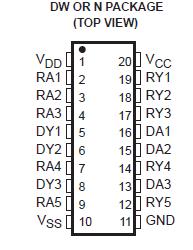
SN75C185: Features: ·Meets or Exceeds the Requirements of TIA/EIA-232-F and ITU Recommendation V.28 · Single Chip With Easy Interface Between UART and Serial-Port Connector·Less Than 9-mW Power Consumption· W...

floor Price/Ceiling Price

Part Number:
SN75C185
Supply Ability:
5000

Price Break

  • Qty
  • 1~5000
  • Unit Price
  • Negotiable
  • Processing time
  • 15 Days
Total Cost: $ 0.00

SeekIC Buyer Protection PLUS - newly updated for 2013!

  • Escrow Protection.
  • Guaranteed refunds.
  • Secure payments.
  • Learn more >>

Month Sales

268 Transactions

Rating

evaluate  (4.8 stars)

Upload time: 2025/12/24

Payment Methods

All payment methods are secure and covered by SeekIC Buyer Protection PLUS.

Notice: When you place an order, your payment is made to SeekIC and not to your seller. SeekIC only pays the seller after confirming you have received your order. We will also never share your payment details with your seller.
Product Details

Description


Features:

·Meets or Exceeds the Requirements of TIA/EIA-232-F and ITU Recommendation V.28
· Single Chip With Easy Interface Between UART and Serial-Port Connector
·Less Than 9-mW Power Consumption
· Wide Driver Supply Voltage . . . 4.5 V to 13.2 V
· Driver Output Slew Rate Limited to 30 V/ms Max
·Receiver Input Hysteresis . . . 1100 mV Typ
·Push-Pull Receiver Outputs
·On-Chip Receiver 1-ms Noise Filter
· Functionally Interchangeable With Texas Instruments SN75185
· Operates Up to 120 kbit/s Over a 3-Meter Cable (See Application Information for Conditions)


Pinout

  Connection Diagram


Specifications

Supply voltage, VDD (see Note 1) . . . . . . . . . . . . . . . . . . . . . .  . . . . . . . . . . . . . . . . . . . . . . . . . . . . . . . 13.5 V
Supply voltage, VSS . . . . . . . . . . . . . . . . . . . . . . . . . . . . . . . . . . . . . . . . . . . . . . . . . . . . . . . . . . . . . . . 13.5 V
Supply voltage, VCC . . . . . . . . . . . . . . . . . . . . . . . . . . . . . . . . . . . . . . . . . . . . . . . . . . . . . . . . . . . . . . . . . . . 7 V
Input voltage range, VI: Driver . . . . . . . . . . . . . .. . . . . . . . . . . . . . . . . . . . . . . . . . . . . . . . . . . . . . . VSS to VDD
                                   Receiver . . . . . . . . . . . . . . . . . . . . . . . . . . . . . . . . . . . . . . . . . . . . . . . . . . 30 V to 30 V
Output voltage range, VO: Driver . . . . . . . . . . . . . . . . . . . . . . . . . . . . . . . . . .  . . . . . . . VSS 6 V to VDD + 6 V
                                      Receiver . . . . . . . . . . . . . . . . . . . . . . . . . . . . . . . . . . . . . . . . . . 0.3 V to VCC + 0.3 V
Package thermal impedance, JA (see Note 2): DW package . . . . . . . . . . . . . . . . . . . . . . . . . . . . .. . 58°C/W
                                                                     N package . . . . . . . . . . . . . . . . . . . . . . . . . . . . . . . . . . . 69°C/W
Operating free-air temperature range, TA . . . . . . . . . . . . . . . . . . . . . . . . . . . . . . . . . . . . . . . . . . 0°C to 70°C
Lead temperature 1,6 mm (1/16 inch) from case for 10 seconds . . . . . . . . . . . . . . . . . . . . . . .  . . . . . . 260°C
Storage temperature range, Tstg . . . . . . . . . . . . . . . . . . . . . . . . . . . . . . . . . . . . . . . . . . . . . 65°C to 150°C
† Stresses beyond those listed under "absolute maximum ratings" may cause permanent damage to the device. These are stress ratings only, and
functional operation of the device at these or any other conditions beyond those indicated under "recommended operating conditions" is not
implied. Exposure to absolute-maximum-rated conditions for extended periods may affect device reliability.
NOTES: 1. All voltages are with respect to network GND.
2. The package thermal impedance is calculated in accordance with JESD 51.


Description

The SN75C185 is a low-power BiMOS device containing three independent drivers and five receivers that are used to interface data terminal equipment (DTE) with data circuit-terminating equipment (DCE). Typically, the SN75C185 replaces one SN75188 and two SN75189 devices. This device conforms to TIA/EIA-232-F. The drivers and receivers of the SN75C185 are similar to those of the SN75C188 and SN75C189A, respectively.

The drivers SN75C185 have a controlled output slew rate that is limited to a maximum of 30 V/ms, and the receivers have filters that reject input noise pulses that are shorter than 1 ms. Both these features eliminate the need for external components.

The SN75C185 uses the low-power BiMOS technology. In most applications, the receivers contained in this device interface to single inputs of peripheral devices such as ACEs, UARTS, or microprocessors. By using sampling, such peripheral devices usually are insensitive to the transition times of the input signals. If this is not the case, or for other uses, it is recommended that the SN75C185 receiver outputs be buffered by single Schmitt input gates or single gates of the HCMOS, ALS, or 74F logic families.

The SN75C185 is characterized for operation from 0°C to 70°C.


Customers Who Bought This Item Also Bought

Margin,quality,low-cost products with low minimum orders. Secure your online payments with SeekIC Buyer Protection.
Industrial Controls, Meters
Isolators
Programmers, Development Systems
Line Protection, Backups
Fans, Thermal Management
Batteries, Chargers, Holders
View more