Features: ·Single-Chip Interface Solution for the 9-Pin GeoPortE Peripheral Data Circuit- Terminating Equipment (DCE) for the
Intelligent Network Port
· Designed to Operate up to 4-Mbits/s Full Duplex
· Single 5-V Supply Operation
· 10-kV ESD Protection on Bus Terminals
· Backward Compatible with AppleTalkE and LocalTalkE LANs
· Combines Multiple Components into a Single Chip Solution
· Complements the SN75LBC776 9-Terminal GeoPort Host Data Terminal Equipment (DTE) Interface Device
· LinBiCMOSETM Process TechnologyPinout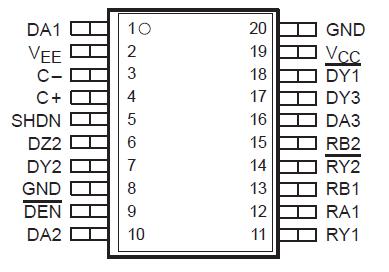 Specifications
Positive supply voltage range, VCC, (see Note 1) ..........................0.5 to 7 V
Negative supply voltage range, VEE, (see Note 1) .........................7 to 0.5 V
Receiver input voltage range (RA1, RB1, RB2)...........................15 V to 15 V
Receiver differential input voltage range, VID ...........................12 V to 12 V
Receiver output voltage range (RY1, RY2) ............................0.5 V to 5.5 V
Driver output voltage range (Power Off)(DY1 , DY2, DZ2, DY3) ..................15 V to 15 V
Driver output voltage range (Power On)(DY1 , DY2, DZ2, DY3) ..................11 V to 11 V
Driver input voltage range (DA, SHDN, DEN )........................0.5 V to VCC +0.4 V
Electrostatic discharge (see Note 2)
Bus Pins (Class 3 A)..10 kV
Bus Pins (Class 3 B) ............................................600 V
All Pins (Class 3, A) .............................................2 kV
All Pins (Class 3 B)............................................. 200 V
Continuous total power dissipation ........................See Dissipation Rating Table
Operating free-air temperature range, TA .............................0°C to 70°C
Storage temperature range, Tstg ..............................65°C to 150 °C
Lead temperature 1,6 mm (1/16 inch) from case for 10 seconds..................... 260°C
† Stresses beyond those listed under "absolute maximum ratings" may cause permanent damage to the device. These are stress ratings only, andfunctional operation of the device at these or any other conditions beyond those indicated under "recommended operating conditions" is not implied. Exposure to absolute-maximum-rated conditions for extended periods may affect device reliability.
NOTES:
1. All voltages values are with respect to the network ground terminal unless otherwise noted.
2. This rating is measured using MIL-STD-883C Method, 3015.7.
DescriptionThe SN75LBC777 is a low-power LinBiCMOS device that incorporate the drivers and receivers for a 9-pin GeoPort peripheral interface. GeoPort combines hybrid EIA/TIA-422-B and EIA/ TIA-423-B drivers and receivers to transmit data up to four-Mbit/s full duplex. GeoPort is a serial communications standard that is intended to replace the RS-232, AppleTalk, and printer ports all in one connector in addition to providing real-time data transfer capability. The SN75LBC777 provides point-to-point connections between GeoPort-compatible devices with data transmission rates up to 4-Mbit/s full duplex over a 4-foot cable. pplications include connection to telephone, integrated services digital network (ISDN), digital sound and imaging, fax-data modems, and other traditional serial and parallel connections. The GeoPort is backwardly compatible to both LocalTalk and AppleTalk LANs.
While the SN75LBC777 is powered off (VCC = 0) the outputs are in a high-impedance state. When the shutdown (SHDN) terminal is high, the charge pump is powered down and the outputs are in a high-impedance state. When high, the driver enable (DEN ) terminal puts the outputs of the differential driver into a high-impedance state.

 SN75LBC777 Data Sheet