SN75LP196

Features: ·Single-Chip RS-232 Interface for an External Modem or Other Computer Peripheral Serial Port·Designed to Transmit and Receive 4-ms Pulses (Equivalent to 256 kbit/s)·Wide Driver Supply-Voltage Range:4.75 V to 15 V·Driver Output Slew Rates Are Controlled Internally to 30 V/ms Maximum·Recei...

product image

SN75LP196 Picture
SeekIC No. : 004499760 Detail

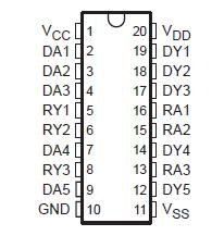
SN75LP196: Features: ·Single-Chip RS-232 Interface for an External Modem or Other Computer Peripheral Serial Port·Designed to Transmit and Receive 4-ms Pulses (Equivalent to 256 kbit/s)·Wide Driver Supply-Volt...

floor Price/Ceiling Price

Part Number:
SN75LP196
Supply Ability:
5000

Price Break

  • Qty
  • 1~5000
  • Unit Price
  • Negotiable
  • Processing time
  • 15 Days
Total Cost: $ 0.00

SeekIC Buyer Protection PLUS - newly updated for 2013!

  • Escrow Protection.
  • Guaranteed refunds.
  • Secure payments.
  • Learn more >>

Month Sales

268 Transactions

Rating

evaluate  (4.8 stars)

Upload time: 2025/12/24

Payment Methods

All payment methods are secure and covered by SeekIC Buyer Protection PLUS.

Notice: When you place an order, your payment is made to SeekIC and not to your seller. SeekIC only pays the seller after confirming you have received your order. We will also never share your payment details with your seller.
Product Details

Description


Features:

·Single-Chip RS-232 Interface for an
    External Modem or Other Computer
    Peripheral Serial Port
·Designed to Transmit and Receive 4-ms
    Pulses (Equivalent to 256 kbit/s)
·Wide Driver Supply-Voltage Range:
   4.75 V to 15 V
·Driver Output Slew Rates Are Controlled
   Internally to 30 V/ms Maximum
·Receiver Input Hysteresis . . . 1000 mV
   Typical
·RS-232 Bus-Pin ESD Protection Exceeds
    15 kV Using Human-Body Model (HBM)
·Five Drivers and Three Receivers Meet or
   Exceed the Requirements of TIA/EIA-232-F
    and ITU v.28 Standards
·Complements the SN75LP1185
·Designed to Replace the Industry-Standard
   SN75196 With the Same Flow-Through
   Pinout
·Package Options Include Plastic Small
   Outline (DW), Shrink Small-Outline (DB),
   Thin Shrink Small-Outline (PW), and
    Dual-in-Line (N) Packages


Pinout

  Connection Diagram


Specifications

Positive supply-voltage range (see Note 1): VCC . . . . . . . . . . . . . .. . . . . . . . . . . . . . . . . . . . . . . . 0.5 V to 7 V
                                                                    VDD (see Note 1) . . . . . . . . . . . . . . . . . . . . . . . . . . . 0.5 V to 15 V
Negative supply-voltage range, VSS (see Note 1) . . . . . . . . . . . . . . . . . . . . . . . . . . . . . . . . . . . . 0.5 V to 15 V
Input-voltage range, VI: Receiver (RA) . . . . . . . . . . . . . . . . . . . . . . . . . . . . . . . . . . . . . . . . . . .  30 V to 30 V
                                Driver (DA) . . . . . . . . . . . . . . . . . . . . . . . . . . . . . . . . . . . . . . . . . . . . . 0.5 V to VCC+0.4 V
Output-voltage range, VO: Receiver (RY) . . . . . . . . . . . . . . . . . . . . . . . . . . . . . . . . . . . . . . . . . . . . 0.5 V to 6 V
                                     Driver (DY) . . . . . . . . . . . . . . . . . . . . . . . . . . . . . . . . . . . . . . . . . . . . . . . . 15 V to 15 V
Electrostatic discharge: Bus pins (human-body model) (see Note 2) . . . . . . . . . . . . . . . . . . . Class 3, A: 15 kV
                                      All pins (human-body model) (see Note 2) . . . . . . . . . . . . . . . . . . . . . . Class 3, A: 5 kV
                                 All pins (machine model) . . . . . . . . . . . . . . . . . . . . . . . . . . . . . . . . . . . . . . . . . . . . . . 200 V
Package thermal impedance, JA (see Notes 3 and 4): DB package . . . . . . . . . . . . . . . . . . . . . . . . . . 115°C/W
                                                                                     DW package . . . . . . . . . . . . . . . . . . . . . . . . . . . 97°C/W
                                                                                      N package . . . . . . . . . . . . . . . . . . . . . . . . . . . . 67°C/W
                                                                                     PW package . . . . . . . . . . . . . . . . . . . . . . . . . . 128°C/W
Lead temperature 1,6 mm (1/16 inch) from case for 10 seconds . . . . . . . . . . . . . . . . . . . . . . . . . . . . . . . 260°C
Storage temperature range, Tstg . . . . . . . . . . . . . . . . . . . . . . . . . . . . . . . . . . . . . . . . . . . . . .  65°C to  150°C
† Stresses beyond those listed under "absolute maximum ratings" may cause permanent damage to the device. These are stress ratings only, and
functional operation of the device at these or any other conditions beyond those indicated under "recommended operating conditions" is not
implied. Exposure to absolute-maximum-rated conditions for extended periods may affect device reliability.
NOTES: 1. All voltage values are with respect to network ground terminal, unless otherwise noted.
2. Per MIL-STD-883 Method 3015.7
3. Maximum power dissipation is a function of TJ(max), qJA, and TA. The maximum allowable power dissipation at any allowable
ambient temperature is PD = (TJ(max) TA)/qJA. Operating at the absolute maximum TJ of 150°C can impact reliability.
4. The package thermal impedance is calculated in accordance with JESD 51, except for through-hole packages, which use a trace length of zero.


Description

The SN75LP196 is a low-power bipolar device containing five drivers and three receivers, with 15 kV of ESD protection on the bus pins with respect to each other. Bus pins are defined as those pins that tie directly to the serial-port connector, including GND. The pinout matches the flow-through design of the industry-standard SN75196 and allows easy interconnection of the UART and serial-port connector of the IBM PC/AT and compatibles. This device provides a rugged, low-cost solution for this function with the combination of bipolar processing and 15-kV ESD protection.

The SN75LP196 has internal slew-rate control to provide a maximum rate of change in the output signal of 30 V/ms. The driver output swing is clamped nominally at ±6 V to enable the higher data rates associated with this device and to reduce EMI emissions. Even though the driver outputs are clamped, they can handle voltages up to ±15 V without damage. All the logic inputs can accept 3.3-V or 5-V input signals.

The SN75LP196 complies with the requirements of the TIA/EIA-232-F and the ITU v.28 standards. These standards are for data interchange between a host computer and peripheral at signaling rates up to 20 kbit/s. The switching speeds of the SN75LP196 support rates up to 256 kbit/s with lower capacitive loads (shorter cables).

The SN75LP196 is characterized for operation from 0°C to 70°C.


Customers Who Bought This Item Also Bought

Margin,quality,low-cost products with low minimum orders. Secure your online payments with SeekIC Buyer Protection.
Potentiometers, Variable Resistors
Connectors, Interconnects
Cables, Wires
Resistors
Optoelectronics
Motors, Solenoids, Driver Boards/Modules
View more