Features: 104 x 64 + 1 Icon LineSingle Supply Operation, 2.4 V - 3.5VMinimum -12.0V LCD Driving Output VoltageLow Current Sleep ModeOn-Chip Voltage Generator or External LCD Driving Power Supply Selectable2X / 3X / 4X/ 5X On-Chip DC-DC ConverterOn-Chip OscillatorOn-Chip Bias Divider with integrate...
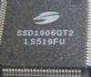
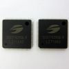
SSD1818: Features: 104 x 64 + 1 Icon LineSingle Supply Operation, 2.4 V - 3.5VMinimum -12.0V LCD Driving Output VoltageLow Current Sleep ModeOn-Chip Voltage Generator or External LCD Driving Power Supply Sel...
SeekIC Buyer Protection PLUS - newly updated for 2013!
268 Transactions
All payment methods are secure and covered by SeekIC Buyer Protection PLUS.
Symbol | Parameter | Value | Unit |
VDD | Supply Voltage | -0.3 to +4.0 | V |
VEE | 0 to -12.0 | V | |
Vin | Input Voltage | VSS-0.3 to VDD+0.3 | V |
I | Current Drain Per Pin Excluding VDD and VSS | 25 | mA |
TA | Operating Temperature | -30 to +85 | °C |
Tstg | Storage Temperature Range | -65 to +150 | °C |
Maximum ratings are those values beyond which damages to the device may occur. Functional operation should be restricted to
the limits in the Electrical Characteristics tables or Pin Description section
This device contains circuitry to protect the inputs against damage due to high static voltages or electric fields; however, it is advised that normal precautions to be taken to avoid application of any voltage higher than maximum rated voltages to this high impedance circuit. For proper operation it is recommended that Vin and Vout be constrained to the range VSS < or = (Vin or Vout) < or = VDD. Reliability of operation is enhanced if unused input are connected to an appropriate logic voltage level (e.g., either VSS or VDD). Unused outputs must be left open. This device may be light sensitive. Caution should be taken to avoid exposure of this device to any light source during normal operation. This device is not radiation protected.
This module SSD1818 determines whether the input signal is interpreted as data or command. Input is directed to this module based on the input of the D/C pin.
If the D/ C pin is high, input is written to Graphic Display Data RAM (GDDRAM). If it is low, the input at D7-D0 is interpreted as a Command. SSD1818 will be decoded and written to the corresponding command register.
The parallel interface of SSD1818 consists of 8 bi-directional data pins (D7-D0), R/W (WR ), D/C , E/(RD), CS1 and CS2.
R/W (WR ) input high indicates a read operation from the Graphic Display Data RAM (GDDRAM) or the status register. In order to match the operating frequency of the GDDRAM with that of the MCU, pipeline processing is internally performed which requires the insertion of a dummy read before the first actual display data read. This is shown in Figure 3.