PinoutDescriptionThe ST7538 is designed as a half duplex synchronous / asynchronous FSK modem designed for power line communication network applications. It operates from a single supply voltage and integrates a line driver and a 5V linear regulator. The ST7538 operation is controlled by means of ...
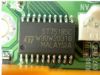
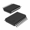
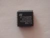
ST7538: PinoutDescriptionThe ST7538 is designed as a half duplex synchronous / asynchronous FSK modem designed for power line communication network applications. It operates from a single supply voltage and...
SeekIC Buyer Protection PLUS - newly updated for 2013!
268 Transactions
All payment methods are secure and covered by SeekIC Buyer Protection PLUS.

The ST7538 is designed as a half duplex synchronous / asynchronous FSK modem designed for power line communication network applications. It operates from a single supply voltage and integrates a line driver and a 5V linear regulator. The ST7538 operation is controlled by means of an internal register, programmable through the synchronous serial interface. Additional functions as watchdog, clock output, output voltage and current control, preamble detection, time-out, band in use are included.
ST7538 has fourteen features. (1) Half duplex frequency shift keying (FSK) transceiver. (2) Integrated power line driver with programmable voltage and current control. (3) Programmable interface of synchronous and asynchronous. (4) Single supply voltage (from 7.5 up to 12.5V). (5) Very low power consumption (Iq=5mA). (6) Integrated 5V voltage regulator (up to 100mA) with short circuit protection. (7) 8 programmable transmission frequencies. (8) Programmable baud rate up to 4800bps. (9) Receiving sensitivity 1mVrms. (10) Suitable to application in accordance with EN 50065 cenelec specifications. (11) Carrier or preamble detection. (12) Band in use detection. (13) Programmable register with security checksum. (14) Mains zero crossing detection and synchronization. That are all the main features.
Some ST7538 absolute maximum ratings have been concluded into several points as follow. (1) Its power supply voltage would be from -0.3 to +14V. (2) Its analog supply voltage would be from -0.3 to +5.5V. (3) Its digital supply voltage would be from -0.3 to +5.5V. (4) Its voltage between AVss and DVss would be from -0.3 to +0.3V. (5) Its digital input voltage would be from DVss-0.3V to DVdd+0.3V. (6) Its digital output voltage would be from DVss-0.3V to DVdd+0.3V. (7) Its digital output current would be from -2mA to +2mA. (8) Its voltage range at Vsense input would be from AVss-0.3V to AVdd+0.3V. And so on. If you have any question or suggestion or want to know more information please contact us for details. Thank you!