Features: Rugged 650 V Avalanche-Rated MOSFET Simplified Surge Absorption No VDSS Derating Required
1.9 Ω rDS(on)
Two Operational Modes by Automatic Switching: PRC Mode for Normal Operation Burst Mode for Stand-By Operation or Light Loads
Built-In Leading Edge Blanking
Low Start-Up Current Start-Up Circuit Disabled in Operation
Low Operating Current (1.5 mA typ)
Automatic Burst Stand-By (intermittent operation) Input Power <0.1 W at No Load
SpecificationsControl Supply Voltage, VCC . . . . . . . . . . . . . .35 V
Drain-Source Voltage, VDSS . . . . . . . . . . . . .. 650 V
Drain Switching Current, ID . . . . . . . . . . . . . . .3.4 A*
Peak Drain Switching Current,
IDM . . . . . . . . . . . . . . . . . . . . . . . . . . . . . . . . . 1.8 A
Single-Pulse Avalanche Energy,
EAS . . . . . . . . . . . . . . . . . . . . . . . . . . . . . . . .136 mJ
Start-Up-Pin Voltage Range,
Vstartup . . . . . . . . . . . . .. . . . . . .. 0.3 V to +600 V
OCP Voltage Range,
VOCP . . . . . . . . . . . . . . . . . . . . . . . .. 0.5 V to +6 V
FB/OLP Voltage Range,
VFB/OLP . . . . . . . . . . . . . . .. . . . . .. 0.5 V to +10 V
Package Power Dissipation, PD
control (VCC * ICC(ON)) . . . . . . . . . . . . . . . 0.46 W
MOSFET (VDSS * ID) . . . . . . . . . . . . . . . .. . 1.81 W
total . . . . . . . . . . . . . . . . . . . . .. . . . . . . .. . 2.27 W
MOSFET Channel Temp., TJ . +150°C
Internal Frame Temp., TF . . . . . . .. . . . . . . +125°C
Operating Temperature Range,
TA . . . . . . . . . . . . . . . . . .. . . . . -20°C to +125°C†
Storage Temperature Range,
TS . . . . . . . . . . . .. . . .. . . . . .. . . -40°C to +125°C
* Drain switching current is limited by temperature
(page 2) and safe operating area
(page 4).
†For the availability of parts meeting -40°C
requirements, contact Allegro's Sales Representative.
- Rugged Avalanche-Rated MOSFET
Simplified Surge Absorption
No VDSS Derating Required
- Choice of rDS(on)
- Two Operational Modes by Automatic Switching:
PRC Mode for Normal Operation
Burst Mode for Stand-By Operation or Light Loads
- Built-In Leading Edge Blanking
- Low Start-Up Current
Start-Up Circuit Disabled in Operation
- Low Operating Current (1.5mAtyp)
- Automatic Burst Stand-By (intermittent operation)
Input Power <0.1W at No Load
- Auto-Bias Function
Stable Burst Operation Without Generating Interference
- Internal Off-Timer Circuit
- Built-In Constant-Voltage Drive
- Multiple Protections:
Pulse-by-Pulse Overcurrent Protection
Overload Protection with Auto Recovery
Latching Overvoltage Protection
Undervoltage Lockout with Hysteresis
Latching Thermal Shutdown
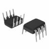
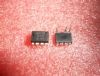
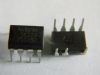
- Molded Small-Size 8-Pin Package
For Low-Height SMPS
Polarized to Prevent Backwards Assembly
The Series STR-A6100 are PRC topology ICs (fixed off-time and variable on-time control) designed for a relatively low output power SMPS design of which output power is up to 20 W at universal input or 24 W at 230 VAC input. The auto-standby function reduces input power consumption to less than 50 mW at 230 VAC input by the burst-mode operation, which is stabilized by the auto-bias function to avoid a hiccup phenomenon. Current-mode feedback and leading-edge blanking stabilize the entire power supply operation. Various protections such as overvoltage, overcurrent, overload, thermal shutdown, and an avalanche-guaranteed MOSFET secure good system-level reliability.
These devices are provided in an 8-pin mini-DIP plastic package.
DescriptionThe Series STR-A6100 are PRC topology ICs (fixed off-time and variable on-time control) designed for a relatively low output power SMPS design of which output power is up to 20 W at universal input or 24 W at 230 VAC input. The auto-standby function reduces input power consumption to less than 50 mW at 230 VAC input by the burst-mode operation, which is stabilized by the auto-bias function to avoid a hiccup phenomenon. Current-mode feedback and leading-edge blanking stabilize the entire power supply operation. Various protections such as overvoltage, overcurrent, overload, thermal shutdown, and an avalanche-guaranteed MOSFET secure good system-level reliability.
These devices are provided in an 8-pin mini-DIP plastic package.

 STR-A6153E Data Sheet