Features: `On-chip clock ÷4 and ÷8`Extended 100E VEE range of 4.2V to 5.5V`2.5Gb/s data rate capability`Differential clock and serial inputs`VBB output for single-ended use`Asynchronous data synchronization`Mode select to expand to 8 bits`Internal 75kΩ input pull-down resistors`Fully compati...
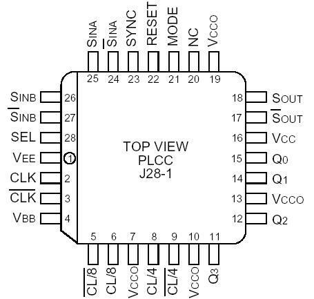
SY100E445: Features: `On-chip clock ÷4 and ÷8`Extended 100E VEE range of 4.2V to 5.5V`2.5Gb/s data rate capability`Differential clock and serial inputs`VBB output for single-ended use`Asynchronous data synchro...
SeekIC Buyer Protection PLUS - newly updated for 2013!
268 Transactions
All payment methods are secure and covered by SeekIC Buyer Protection PLUS.
DescriptionThe SY10/100E111 are low skew 1-to-9 differential drivers designed for clock distributi...

The SY10/SY100E445 are integrated 4-bit serial-to-parallel data converters. The devices are designed to operate for NRZ data rates of up to 2.5Gb/s. The SY100E445 generates a divide-by-4 and a divide-by-8 clock for both 4-bit conversion and a two-chip 8-bit conversion function. The conversion sequence was chosen to convert the first serial bit to Q0, the second to Q1, etc.
Two selectable serial inputs provide a loopback capability for testing purposes when the SY100E445 is used in conjunction with the E446 parallel-to-serial converter.
The start bit for conversion can be moved using the SY100E445 input. A single pulse, applied asynchronously for at least two input clock cycles, shifts the start bit for conversion from Qn to Qn-1 by one bit. For each additional shift required, an additional pulse must be applied to the SYNC input. Asserting the SYNC input will force the internal clock dividers to "swallow" a clock pulse, effectively shifting a bit from the Qn to the Qn-1 output (see Timing Diagram B).
The MODE input of SY100E445 is used to select the conversion mode of the device. With the MODE input LOW (or open) the device will function as a 4-bit converter. When the mode input is driven HIGH, the data on the output will change on every eighth clock cycle, thus allowing for an 8-bit conversion scheme using two SY100E445. When cascaded in an 8-bit conversion scheme, the devices will not operate at the 2.5Gb/s data rate of a single device. Refer to the applications section of this data sheet for more information on cascading the SY100E445.
For lower data rate applications, a VBB of SY100E445 reference voltage is supplied for single-ended inputs. When operating at clock rates above 500MHz, differential input signals are recommended. For single-ended inputs, the VBB pin is tied to the inverting differential input and bypassed via a 0.01µF capacitor. The VBB of SY100E445 provides the switching reference for the input differential amplifier. The VBB can also be used to AC couple an input signal.