T89C51CC02

Features: • 80C51 Core Architecture• 256 Bytes of On-chip RAM• 256 Bytes of On-chip XRAM• 16K Bytes of On-chip Flash Memory Data Retention: 10 Years at 85°C Erase/Write Cycle: 100K• Boot Code Section with Independent Lock Bits• 2K Bytes of On-chip Flash for Boot...

product image

T89C51CC02 Picture
SeekIC No. : 004511587 Detail

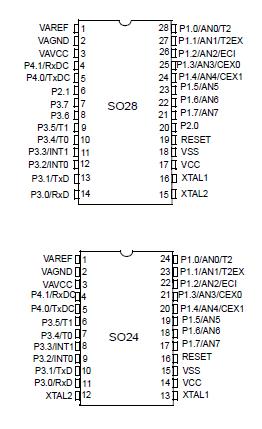
T89C51CC02: Features: • 80C51 Core Architecture• 256 Bytes of On-chip RAM• 256 Bytes of On-chip XRAM• 16K Bytes of On-chip Flash Memory Data Retention: 10 Years at 85°C Erase/Write Cycle...

floor Price/Ceiling Price

Part Number:
T89C51CC02
Supply Ability:
5000

Price Break

  • Qty
  • 1~5000
  • Unit Price
  • Negotiable
  • Processing time
  • 15 Days
Total Cost: $ 0.00

SeekIC Buyer Protection PLUS - newly updated for 2013!

  • Escrow Protection.
  • Guaranteed refunds.
  • Secure payments.
  • Learn more >>

Month Sales

268 Transactions

Rating

evaluate  (4.8 stars)

Upload time: 2024/4/26

Payment Methods

All payment methods are secure and covered by SeekIC Buyer Protection PLUS.

Notice: When you place an order, your payment is made to SeekIC and not to your seller. SeekIC only pays the seller after confirming you have received your order. We will also never share your payment details with your seller.
Product Details

Description


Features:

• 80C51 Core Architecture
• 256 Bytes of On-chip RAM
• 256 Bytes of On-chip XRAM
• 16K Bytes of On-chip Flash Memory
Data Retention: 10 Years at 85°C
Erase/Write Cycle: 100K
• Boot Code Section with Independent Lock Bits
• 2K Bytes of On-chip Flash for Bootloader
• In-System Programming by On-Chip Boot Program (CAN, UART) and IAP Capability
• 2K Bytes of On-chip EEPROM
Erase/Write Cycle: 100K
• 14-sources 4-level Interrupts
• Three 16-bit Timers/Counters
• Full Duplex UART Compatible 80C51
• Maximum Crystal Frequency 40 MHz. In X2 Mode, 20 MHz (CPU Core, 40 MHz)
• Three or Four Ports: 16 or 20 Digital I/O Lines
• Two-channel 16-bit PCA
PWM (8-bit)
High-speed Output
Timer and Edge Capture
• Double Data Pointer
• 21-bit Watchdog Timer (7 Programmable bits)
• A 10-bit Resolution Analog-to-Digital Converter (ADC) with 8 Multiplexed Inputs
• Full CAN Controller
Fully Compliant with CAN rev.# 2.0A and 2.0B
Optimized Structure for Communication Management (Via SFR)
4 Independent Message Objects
-Each Message Object Programmable on Transmission or Reception
-Individual Tag and Mask Filters up to 29-bit Identifier/Channel
-8-byte Cyclic Data Register (FIFO)/Message Object
-16-bit Status and Control Register/Message Object
-16-bit Time-Stamping Register/Message Object
-CAN Specification 2.0 Part A or 2.0 Part B Programmable for Each Message Object
-Access to Message Object Control and Data Registers Via SFR
-Programmable Reception Buffer Length up to 4 Message Objects
-Priority Management of Reception of Hits on Several Message Objects Simultaneously (Basic CAN Feature)
-Priority Management for Transmission
-Message Object Overrun Interrupt
Supports
-Time Triggered Communication
-Autobaud and Listening Mode
-Programmable Automatic Reply Mode
• 1-Mbit/s Maximum Transfer Rate at 8 MHz(1) Crystal Frequency In X2 Mode
• Readable Error Counters
• Programmable Link to On-chip Timer for Time Stamping and Network Synchronization
• Independent Baud Rate Prescaler
• Data, Remote, Error and Overload Frame Handling
• Power-saving Modes
Idle Mode
Power-down Mode
• Power Supply: 3 Volts to 5.5 Volts
• Temperature Range: Industrial (-40° to +85°C)
• Packages: SOIC28, SOIC24, PLCC28, VQFP32


Application

Software can take advantage of the additional data pointers to both increase speed and reduce code size, for example, block operations (copy, compare.) are well served by using one data pointer as a "source" pointer and the other one as a "destination" pointer.

Hereafter is an example of block move implementation using the two pointers and coded in assembler. The latest C compiler takes also advantage of this feature by providing enhanced algorithm libraries.

The INC instruction is a short (2 Bytes) and fast (6 machine cycle) way to manipulate the DPS bit in the AUXR1 register. However, note that the INC instruction does not directly force the DPS bit to a particular state, but simply toggles it. In simple routines, such as the block move example, only the fact that DPS is toggled in the proper sequence matters, not its actual value. In other words, the block move routine works the same whether
DPS is 0 or 1 on entry.


Pinout

  Connection Diagram  Connection Diagram


Specifications

I = industrial ................................................. -40°C to 85°C
Storage Temperature .............................. -65°C to + 150°C
Voltage on VCC from VSS ...................................-0.5V to + 6V
Voltage on Any Pin from VSS ....................-0.5V to VCC + 0.2V
Power Dissipation ............................................................ 1 W


Description

Part of the CANaryTM family of 8-bit microcontrollers dedicated to CAN network applications, the T89C51CC02 is a low-pin count 8-bit Flash microcontroller.

In X2 Mode a maximum external clock rate of 20 MHz reaches a 300 ns cycle time.

Besides the full CAN controller T89C51CC02 provides 16K Bytes of Flash memory including In-System Programming (ISP), 2K Bytes Boot Flash Memory, 2K Bytes EEPROM and 512 Bytes RAM.

Special attention is payed to the reduction of the electro-magnetic emission of T89C51CC02.


Customers Who Bought This Item Also Bought

Margin,quality,low-cost products with low minimum orders. Secure your online payments with SeekIC Buyer Protection.
Undefined Category
Discrete Semiconductor Products
Motors, Solenoids, Driver Boards/Modules
LED Products
Power Supplies - Board Mount
View more