Features: ` Built-in preamplifier
Input coupling condenser-less
Built-in input capacitor for reducing buzz noise
Low noise: Vni = 1.2 Vrms (typ.)
Preamplifier on/off switch.
` Built-in power amplifier
OCL (Output condenser-less)
Voltage gain: GV = 31 dB (typ.)
` Built-in motor governor (Current proportion type)
` Built-in DC volume control function
ATT = 82dB (Ta = 25, typ.)
` Built-in bass boost function
` Low supply current (VCC = 3 V, f = 1 kHz, PRE OUT = 100 mVrms, Ta = 25, typ.)
` Quiescent supply current
PRE + PW: ICCQ = 8.5 mA
GVN: ICC = 2.5 mA
` 0.1 mW * 2 ch output
ICC1 = 9.8 mA (RL = 32 )
ICC2 = 10.5 mA (RL = 16 )
` 0.5 mW * 2 ch output
ICC3 = 14.0 mA (RL = 32 )
ICC4 = 16.5 mA (RL = 16 )
` Operating supply voltage range (Ta = 25)
VCC (opr) = 1.8~3.6 V
GVN VCC (opr) = 2.1~3.6 V (Motor voltage = 1.8 V)
Application` VCC and GND
This IC has two VCC terminals and three GND terminals. Pattern layout should be designed carefully to reduce the common impedance. VCC
` VCC (pin 17)-----------------Preamplifier stage and power amplifier stage.
GVN VCC (pin 16) ---------Motor governor stage.
` GND
PRE GND (pin 1)------------Preamplifier stage, and power amplifier stage except for the power drive stage.
PW GND (pin 11)-----------Power drive stage of power amplifier.
GVN GND (pin 12)---------Motor governor stage.
` VREF
It is necessary to stabilize the VREF circuit, because the internal circuit operate on this reference.
` RF IN
As this terminal is an input terminal of the ripple filter, it cannot supply a power supply to other ICs etc.
` Preamplifier
Input signal should be applied to VREF standard, otherwise pop noise become bigger when VCC is turned on and off. Power amplifier It is necessary to insert the coupling capacitor through the PW IN terminal. In case that DC current or DC voltage is applied to the PW IN terminal, the internal circuit has unbalance and the power amplifier doesn't perate normally.
` Operating supply voltage range of motor governor stage
As for the minimum of operating supply voltage range, the motor voltage is 1.8 V.
In case that it is more than 1.8 V, the low voltage performance becomes bad.
` PRE SW sensitivity (Ta = 25)
Specifications
|
Characteristics |
Symbol |
Rating |
Unit |
| Supply voltage |
VCC |
4 |
V |
| Power dissipation |
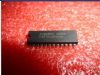
TA2132BP |
PD |
(Note 1) |
400 |
mW |
|
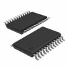
TA2132BF |
(Note 2) |
925 |
|
Output current (PW AMP.) |
IO (PW) |
200 |
mA |
|
Output current (GVN) |
IO (GVN) |
700 |
mA |
| Operating temperature |
Topr |
-25 ~ 75 |
|
| Storage temperature |
Tstg |
-55 ~ 150 |
|
Note 1: IC only: Derated above Ta 25 in the proportion 3.2 mW/
Note 2: IC + PCB (TOSHIBA typical PCB): Derated above Ta = 25 in the proportion7.4 mW/
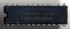
DescriptionThe TA2145AF is developed for play-back stereo headphone equipments (3 V USE).
It is built in dual preamplifiers, dual OCL power amplifiers, motor governor, DC volume control and preamplifier on/off switch etc.

 TA2145AF Data Sheet