TOP200-4

ApplicationKeep the SOURCE pin length very short. Use a Kelvin connection to the SOURCE pin for the CONTROL pin bypass capacitor. Use single point grounding techniques at the SOURCE pin as shown in Figure 11.Minimize peak voltage and ringing on the DRAIN voltage at turn-off. Use a Zener or TVS Zen...

product image

TOP200-4 Picture
SeekIC No. : 004525671 Detail

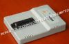
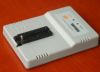
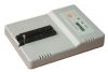
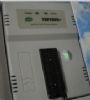
TOP200-4: ApplicationKeep the SOURCE pin length very short. Use a Kelvin connection to the SOURCE pin for the CONTROL pin bypass capacitor. Use single point grounding techniques at the SOURCE pin as shown in ...

floor Price/Ceiling Price

Part Number:
TOP200-4
Supply Ability:
5000

Price Break

  • Qty
  • 1~5000
  • Unit Price
  • Negotiable
  • Processing time
  • 15 Days
Total Cost: $ 0.00

SeekIC Buyer Protection PLUS - newly updated for 2013!

  • Escrow Protection.
  • Guaranteed refunds.
  • Secure payments.
  • Learn more >>

Month Sales

268 Transactions

Rating

evaluate  (4.8 stars)

Upload time: 2024/4/18

Payment Methods

All payment methods are secure and covered by SeekIC Buyer Protection PLUS.

Notice: When you place an order, your payment is made to SeekIC and not to your seller. SeekIC only pays the seller after confirming you have received your order. We will also never share your payment details with your seller.
Product Details

Description


Application

Keep the SOURCE pin length very short. Use a Kelvin connection to the SOURCE pin for the CONTROL pin bypass capacitor. Use single point grounding techniques at the SOURCE pin as shown in Figure 11.

Minimize peak voltage and ringing on the DRAIN voltage at turn-off. Use a Zener or TVS Zener diode to clamp the DRAIN voltage.

Do not plug the TOPSwitch device into a "hot" IC socket during test. External CONTROL pin capacitance may deliver a surge current sufficient to trigger the
shutdown latch which turns the TOPSwitch off.

Under some conditions, externally provided bias or supply current driven into the CONTROL pin can hold the TOPSwitch in one of the 8 auto-restart cycles indefinitely and prevent starting. Shorting the CONTROL pin to the SOURCE pin will reset the TOPSwitch. To avoid this problem when doing bench evaluations, it is recommended that the VC power supply be turned on before the DRAIN voltage is applied.

CONTROL pin currents during autorestart operation are much lower at low input voltages (< 20 V) which increases the auto-restart cycle period (see the IC
vs. Drain Voltage Characteristic curve). Short interruptions of AC power may cause TOPSwitch to enter the 8-count auto-restart cycle before starting again. This is because the input energy storage capacitors are not completely discharged and the CONTROL pin capacitance has not discharged below the pin internal power-up reset voltage.

In some cases, minimum loading may be necessary to keep a lightly loaded or unloaded output voltage within the desired range due to the minimum ONtime.

For additional applications information regarding the TOPSwitch family, refer to AN-14.


Specifications

DRAIN Voltage ............................................ -0.3 to 700 V
CONTROL Voltage ....................................... - 0.3 V to 9 V
Storage Temperature ................................ -65 to 125°C
Operating Junction Temperature(2) ........... -40 to 150°C
Lead Temperature(3) ........................................... 260°C
Thermal Impedance (JA) ................................... 70°C/W
Thermal Impedance (JC)(4) ............................... 2 °C/W
1. Unless noted, all voltages referenced to SOURCE, TA = 25°C.
2. Normally limited by internal circuitry.
3. 1/16" from case for 5 seconds.
4. Measured at tab closest to plastic interface.


Description

The TOP200-4 Switch family implements, with only three pins, all functions necessary for an off-line switched mode control system: high voltage N-channel power MOSFET with controlled turn-on gate driver, voltage mode PWM controller with integrated 100 kHz oscillator, high voltage start-up bias circuit, bandgap derived reference, bias shunt regulator/error amplifier for loop compensation and fault protection circuitry. Compared to discrete MOSFET and controller or self oscillating (RCC) switching converter solutions, a TOPSwitch integrated circuit can reduce total cost, component count, size, weight and at the same time increase efficiency and system reliability. These TOP200-4 devices are intended for 100/110/230 VAC off-line Power Supply applications in the 0 to 100 W (0 to 50 W universal) range and 230/277 VAC off-line power factor correction (PFC) applications in the 0 to 150 W range.


Customers Who Bought This Item Also Bought

Margin,quality,low-cost products with low minimum orders. Secure your online payments with SeekIC Buyer Protection.
Motors, Solenoids, Driver Boards/Modules
Programmers, Development Systems
Industrial Controls, Meters
Power Supplies - Board Mount
Tapes, Adhesives
803
RF and RFID
View more