TPIC0298

Features: • Formerly TLP298• 2-A Output Current Capability Per Full-H Driver• Applications Include Half-H and Full-H Solenoid Drivers and Motor Drivers• Wide Range of Output Supply Voltage 5 V to 46 V• Separate Input-Logic Supply Voltage Thermal Shutdown• Intern...

product image

TPIC0298 Picture
SeekIC No. : 004526340 Detail

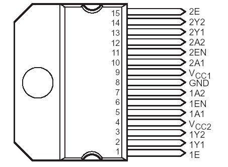
TPIC0298: Features: • Formerly TLP298• 2-A Output Current Capability Per Full-H Driver• Applications Include Half-H and Full-H Solenoid Drivers and Motor Drivers• Wide Range of Output ...

floor Price/Ceiling Price

Part Number:
TPIC0298
Supply Ability:
5000

Price Break

  • Qty
  • 1~5000
  • Unit Price
  • Negotiable
  • Processing time
  • 15 Days
Total Cost: $ 0.00

SeekIC Buyer Protection PLUS - newly updated for 2013!

  • Escrow Protection.
  • Guaranteed refunds.
  • Secure payments.
  • Learn more >>

Month Sales

268 Transactions

Rating

evaluate  (4.8 stars)

Upload time: 2024/4/25

Payment Methods

All payment methods are secure and covered by SeekIC Buyer Protection PLUS.

Notice: When you place an order, your payment is made to SeekIC and not to your seller. SeekIC only pays the seller after confirming you have received your order. We will also never share your payment details with your seller.
Product Details

Description


Features:

• Formerly TLP298
• 2-A Output Current Capability Per Full-H Driver
• Applications Include Half-H and Full-H Solenoid Drivers and Motor Drivers
• Wide Range of Output Supply Voltage 5 V to 46 V
• Separate Input-Logic Supply Voltage Thermal Shutdown
• Internal Electrostatic Discharge Protection
• High Noise Immunity
• 3-State Outputs
• Minimized Power Dissipation
• Sink/Source Interlock Circuitry Prevents Simultaneous Conduction
• Improved Functional Replacement for the SGS L298


Pinout

  Connection Diagram


Specifications

Logic supply voltage range, VCC1 (see Note 1)  . . . . . . . . . . . . . . . . . . . . . . . . . . . . . . . . . . . . . . . .0.3 V to 7 V
Output supply voltage range, VCC2  . . . . . . . . . . . . . . . . . . . . . . . . . . . . . . . . . . . . . . . . . . . . . . . .0.3 V to 50 V
Input voltage range at A or EN, VI (see Note 2) . . . . . . . . . . . . . . . . . . . . . . . . . . . . . . . . . . . . . . . .1.6 V to 7 V
Output voltage range, VO  . . . . . . . . . . . . . . . . . . . . . . . . . . . . . . . . . . . . . . . . . . . . . . . . . . . .2 V to VCC2 + 2 V
Emitter terminal (1E and 2E) voltage range, VE . . . . . . . . . . . . . . . . . . . . . . . . . . . . . . . . . . . . . . .0.5 V to 2.3 V
Emitter terminal (1E and 2E) voltage (nonrepetitive, tw 3 50 ms) . . . . . . . . . . . . . . . . . . . . . . . . . . . . . . . . . 1 V
Input current at A or EN, II  . . . . . . . . . . . . . . . . . . . . . . . . . . . . . . . . . . . . . . . . . . . . . . . . . . . . . . . . . . . .15 mA
Peak output current, IOM: (nonrepetitive, tw 3 0.1 ms)  . . . . . . . . . . . . . . . . . . . . . . . . . . . . . . . . . . . . . . . . .±3 A
                                         (repetitive, tw 3 10 ms, duty cycle 3 80%)  . . . . . . . . . . . . . . . . . . . . . . . . . . . . .±2.5 A
Continuous output current, IO. . . . . . . . . . . . . . . . . . . . . . . . . . . . . . . . . . . . . . . . . . . . . . . . . . . . . . . . . . . .  ±2 A
Peak combined output current for each full-H driver (see Note 3):
                                         (nonrepetitive, tw 3 0.1 ms)  . . . . . . . . . . . . . . . . . . . . . . . . . . . . . . . . . . . . . . .  . .±3 A
                                         (repetitive, tw 3 10 ms, duty cycle 3 80%)  . . . . . . . . . . . . . . . . . . . . . . . . .  . . . .±2.5 A
Continuous combined output current for each full-H driver (see Note 3)  . . . . . . . . . . . . . . . . . . . . . . . . . . . . ±2 A
Continuous dissipation at (or below) 25°C free-air temperature (see Note 4)  . . . . . . . . . . . . . . . . . . . .  3.575 W
Continuous dissipation at (or below) 75°C case temperature (see Note 4)  . . . . . . . . . . . . . . . . . . . . . . . . . 25 W
Operating free-air, case, or virtual junction temperature range . . . . . . . . . . . . . . . . . . . . . . . . . . .40°C to 150°C
Storage temperature range . . . . . . . . . . . . . . . . . . . . . . . . . . . . . . . . . . . . . . . . . . . . . . . . . . . . . . 65°C to 150°C
Lead temperature 1,6 mm (1/16 inch) from case for 10 seconds . . . . . . . . . . . . . . . . . . . . . . . . . . . . . . . . . .260°C


Description

The TPIC0298 is a dual high-current full-H driver designed to provide bidirectional drive currents of up to 2 A at voltages from 5 V to 46 V. It is designed to drive inductive loads such as relays, solenoids, dc motors, stepping motors, and other highcurrent or high-voltage loads in positive-supply applications. All inputs of TPIC0298 are TTL compatible. Each output (Y) is a complete totem-pole drive with a Darlington transistor sink and a pseudo- Darlington source. Each full-H driver is enabled separately. Outputs 1Y1 and 1Y2 are enabled by 1EN and outputs 2Y1 and 2Y2 are enabled by 2EN. When an EN input is high, the associated channels are active. When an EN input is low, the associated channels are off (i.e., in the highimpedance state).

Each half of the TPIC0298 device forms a full-H reversible driver suitable for solenoid or motor applications. The current in each full-H driver can be monitored by connecting a resistor between the sense output terminal 1E and GND and another resistor between sense output terminal 2E and GND.

External high-speed output-clamp diodes should be used for inductive transient suppression. To minimize device power dissipation, a VCC1 supply voltage, separate from VCC2, is provided for the logic inputs. The TPIC0298 is designed for operation from 0°C to 70°C.


Customers Who Bought This Item Also Bought

Margin,quality,low-cost products with low minimum orders. Secure your online payments with SeekIC Buyer Protection.
Test Equipment
Tapes, Adhesives
803
Undefined Category
Connectors, Interconnects
View more