TPPM0115

Features: DC-DC Synchronous Buck ControllerSwitching Frequency, 200 kHz (Typ)Programmable Output Voltage, 1 V to 2.5 V ±2%Power Good Function (PWRGD)Input Voltage, 12 V ±5%Drive High Load Current With External ComponentsApplicationPC Motherboard, Voltage Regulation for System PowerDDR Memory Suppl...

product image

TPPM0115 Picture
SeekIC No. : 004526449 Detail

TPPM0115: Features: DC-DC Synchronous Buck ControllerSwitching Frequency, 200 kHz (Typ)Programmable Output Voltage, 1 V to 2.5 V ±2%Power Good Function (PWRGD)Input Voltage, 12 V ±5%Drive High Load Current Wi...

floor Price/Ceiling Price

Part Number:
TPPM0115
Supply Ability:
5000

Price Break

  • Qty
  • 1~5000
  • Unit Price
  • Negotiable
  • Processing time
  • 15 Days
Total Cost: $ 0.00

SeekIC Buyer Protection PLUS - newly updated for 2013!

  • Escrow Protection.
  • Guaranteed refunds.
  • Secure payments.
  • Learn more >>

Month Sales

268 Transactions

Rating

evaluate  (4.8 stars)

Upload time: 2024/4/26

Payment Methods

All payment methods are secure and covered by SeekIC Buyer Protection PLUS.

Notice: When you place an order, your payment is made to SeekIC and not to your seller. SeekIC only pays the seller after confirming you have received your order. We will also never share your payment details with your seller.
Product Details

Description


Features:

 DC-DC Synchronous Buck Controller
 Switching Frequency, 200 kHz (Typ)
 Programmable Output Voltage, 1 V to 2.5 V ±2%
 Power Good Function (PWRGD)
 Input Voltage, 12 V ±5%
 Drive High Load Current With External Components


Application

 PC Motherboard, Voltage Regulation for System Power
 DDR Memory Supply (VDDQ or VTT)
 RDRAM Memory Supply (VDDQ)
 General Purpose Synchronous Switch Mode Controller


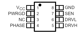
Pinout

  Connection Diagram


Specifications

Unregulated input voltage, VCC (see Notes 1 and 2)  . . . . . . . . . . . . . . . . . . . . . . . . . . . . . .24 V
Drive output voltage, V(DRVH) and V(DRVL) (see Notes 1 and 3)  . . . . . . . . . . . . . . . . . . . .12.6 V
Power good voltage, V(PWRGD) (see Notes 1 and 2) . . . . . . . . . . . . . . . . . . . . . . . . . . . . . . . .7 V
Feedback voltage, V(SEN) (see Notes 1 and 2)  . . . . . . . . . . . . . . . . . . . . . . . . . . . . . . . . . . . .7 V
Phase sense voltage, V(PHASE) (see Note 3)  . . . . . . . . . . . . . . . . . . . . . . . . . . . . . . . . . . . . .7 V
Continuous power dissipation, PD . . . . . . . . . . . . . . . . . . . . . . . . . . . . . . . . . . . . . . . . . . . .0.4 W
Electrostatic discharge susceptibility, V(HBMESD) (see Note 4) . . . . . . . . . . . . . . . . . . . . . . . .2 kV
Operating ambient temperature range, TA . . . . . . . . . . . . . . . . . . . . . . . . . . . . . . . .0°C to 70°C
Storage temperature range, Tstg  . . . . . . . . . . . . . . . . . . . . . . . . . . . .. . . . . . . .65°C to 150°C
Lead temperature (soldering, 10 sec) TLEAD  . . . . . . . . . . . . . . . . . . . . . . . . . . . . . . . . . . .260°C


Description

The TPPM0115 is a synchronous buck controller capable of driving two external power FETs 180° out of phase. The device requires a minimum of external standard filter components and switching FETs to regulate the desired output voltage. This is achieved with an internal switching frequency of 200 kHz (typical).

The TPPM0115 switch mode controller and associated circuitry provide efficient voltage regulation of greater than 85%. The output voltage is set by two external resistors. During power up, when the output voltage reaches 90% of the desired value, the power good (PWRGD) output is transitioned high after a short delay of 1 ms to 5 ms. During power down, when the output voltage falls below 90% of the set value, the PWRGD output is pulled low without any delay.

In the event the set output is in an over-voltage condition due to a system fault, the drive to the lower FET turns on to correct the fault. There is a dead time between switching one FET ON while the other FET is switching OFF to prevent cross conduction. The TPPM0115 is capable of driving high static load currents with minimal ripple on the output (<2%). The phase sense input is used to sense the flow of current through the inductor during flyback to minimize ripple on the output.To optimize output filter capacitance, the voltage mode control is based on a fixed ON time during the start of the cycle and hysteretic control during load transients. This allows the device to respond and maintain the set regulation voltage.


Customers Who Bought This Item Also Bought

Margin,quality,low-cost products with low minimum orders. Secure your online payments with SeekIC Buyer Protection.
Inductors, Coils, Chokes
Circuit Protection
RF and RFID
Optoelectronics
View more