Emitter- Base Voltage VEBO
:
Collector- Base Voltage VCBO
:
Maximum Collector Cut-off Current
:
Power Dissipation
:
Configuration
: Array 7
Transistor Polarity
: NPN
Collector- Emitter Voltage VCEO Max
: 50 V
Maximum Operating Temperature
: + 105 C
Mounting Style
: Through Hole
Packaging
: Tube
Maximum DC Collector Current
: 0.5 A
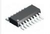
Package / Case
: PDIP-16
Features: · 500-mA-Rated Collector Current (Single Output)
· High-Voltage Outputs . . . 50 V
· Output Clamp Diodes
· Inputs Compatible With Various Types of Logic
· Relay-Driver ApplicationsPinout SpecificationsCollector-emitter voltage . . . . . . . . . . . . . . . . . . . . . . . . . . . . . . . . . . . . . . . . . . . . . . . . . . . . . . ... . . 50 V
Clamp diode reverse voltage (see Note 1) . . . . . . . . . . . . . . . . . . . . . . . . . . . . . . . . . . . . . . . . . .. . . 50 V
Input voltage, VI (see Note 1) . . . . . . . . . . . . . . . . . . . . . . . . . . . . . . . . . . . . . . . . . . . . . . . . . . . . .. 30 V
Peak collector current (see Figures 14 and 15) . . . . . . . . . . . . . . . . . . . . . . . . . . . . . . . . . . . . . . . 500 mA
Output clamp current, IOK . . . . . . . . . . . . . . . . . . . . . . . . . . . . . . . . . . . . . . . . . . . . . . . . . . . . . . . 500 mA
Total emitter-terminal current . . . . . . . . . . . . . . . . . . . . . . . . . . . . . . . . . . . . . . . . . . . . . . . . . . . . . −2.5 A
Operating free-air temperature range, TA, ULN200xA . . . . . . . . . . . . . . . . . . . . . . . . . . . . . . −20 to 70
ULQ200xA . . . . . . . . . . . . . . . . . . . . . . . . . . . . . . −40 to 85
ULQ200xAT . . . . . . . . . . . . . . . . . . . . . . . . . . . . −40 to 105
Package thermal impedance, JA (see Notes 2 and 3): D package . . . . . . . . . . . . . . . . . . . . .. . ... . 73/W
N package . . . . . . . . . . . . . . . . . . . . . . . . .. 67/W
NS package . . . . . . . . . . . . . . . . . . . . . . .. . 64/W
PW package . . . . . . . . . . . . . . . . . . . . . . . 108/W
Package thermal impedance, JC (see Notes 4 and 5): D package . . . . . . . . . . . . . . . . . . . . . .. . . . 36/W
N package . . . . . . . . . . . . . . . . . . . . . . .. ... 54/W
Operating virtual junction temperature, TJ . . . . . . . . . . . . . . . . . . . . . . . . . . . . . . . . . . . . . . . . . . . . . 150
Lead temperature 1,6 mm (1/16 inch) from case for 10 seconds . . . . . . . . . . . . . . . . . . . . . . . . . . . . 260
Storage temperature range, Tstg . . . . . . . . . . . . . . . . . . . . . . . . . . . . . . . . . . . . . . . . .. . . . . −65 to 150
† Stresses beyond those listed under "absolute maximum ratings" may cause permanent damage to the device. These are stress ratings only, and functional operation of the device at these or any other conditions beyond those indicated under "recommended operating conditions" is not implied. Exposure to absolute-maximum-rated conditions for extended periods may affect device reliability.
NOTES: 1. All voltage values are with respect to the emitter/substrate terminal E, unless otherwise noted.
2. Maximum power dissipation is a function of TJ(max), JA, and TA. The maximum allowable power dissipation at any allowable ambient temperature is PD = (TJ(max) − TA)/JA. Operating at the absolute maximum TJ of 150 can affect reliability.
3. The package thermal impedance is calculated in accordance with JESD 51-7.
4. Maximum power dissipation is a function of TJ(max), JC, and TC. The maximum allowable power dissipation at any allowable case temperature is PD = (TJ(max) − TC)/JC. Operating at the absolute maximum TJ of 150 can affect reliability.
5. The package thermal impedance is calculated in accordance with MIL-STD-883.DescriptionThe ULN2001A, ULN2002A, ULN2003A, ULN2004A, ULQ2003A, and ULQ2004A are high-voltage, high-current Darlington transistor arrays. Each consists of seven npn Darlington pairs that feature high-voltage outputs with common-cathode clamp diodes for switching inductive loads. The collector-current rating of a single Darlington pair is 500 mA. The Darlington pairs can be paralleled for higher current capability. Applications include relay drivers, hammer drivers, lamp drivers, display drivers (LED and gas discharge), line drivers, and logic buffers. For 100-V (otherwise interchangeable) versions of the ULN2003A and ULN2004A, see the SN75468 and SN75469, respectively.
The ULN2001A is a general-purpose array and can be used with TTL and CMOS technologies. The ULN2002A is designed specifically for use with 14-V to 25-V PMOS devices. Each input of this device has a Zener diode and resistor in series to control the input current to a safe limit. The ULN2003A and ULQ2003A have a 2.7-k series base resistor for each Darlington pair for operation directly with TTL or 5-V CMOS devices. The ULN2004A and ULQ2004A have a 10.5-k series base resistor to allow operation directly from CMOS devices that use supply voltages of 6 V to 15 V. The required input current of the ULN/ULQ2004A is below that of the ULN/ULQ2003A, and the required voltage is less than that required by the ULN2002A.
Parameters: | Technical/Catalog Information | ULQ2003A |
| Vendor | STMicroelectronics |
| Category | Integrated Circuits (ICs) |
| Number of Drivers/Receivers | 7/0 |
| Type | Darlington Array |
| Voltage - Supply | - |
| Package / Case | 16-DIP (300 mil) |
| Packaging | Tube |
| Protocol | - |
| Drawing Number | * |
| Lead Free Status | Lead Free |
| RoHS Status | RoHS Compliant |
| Other Names | ULQ2003A
ULQ2003A
497 2358 5 ND
49723585ND
497-2358-5
|

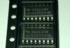
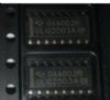
 ULQ2003A Data Sheet