

Project Solutions
A dipole antenna for 4 meters (2)
Published:2011/7/24 22:23:00 Author:Phyllis From:SeekIC
Receiver
sensitivity measurement
With the generator tuned to the receiver (or was it the other v/ay around?) a great moment arrives — v/e’re ready to decrease the RF output level on the generator until the receiver under investigation loses the signal. The VHF-Low Explorer not having an adjustable squelch or squelch defeat switch, the transition from ’very noisy signal’ to ’muted’ was found to be fairly abrupt (more about this further on).
Receiver sensitivity is defined as the RF signal level at which the receiver’s audio output signal achieves a certain signal-to-noise ratio. For NBFM receivers, SINAD = 12 dB is considered the standard — meaning that the signal we would like to hear is 12 dB above the sum of noise and distortion (hence the acronym SINAD; an older measurement standard, S/N, employs noise only in the quotient). The RF signal level is usually given in microvolts pd (potential difference) although emf (electromotive force) is preferred by purists. The CMS 54, then, had its RF signal output connected to the receiver input (by a length of RG58 coax cable) and the audio input, to the receiver’s audio output. After a manual adjustment of the volume control on the receiver, an automated measurement is started on the CMS 54 which steps down its RF signal level until it measures an audio signal of 12 dB SINAD. The RF signal level at which that happens is frozen and displayed — see screendump A. In our case, a sensitivity of about 1.7 microvolts for J 2 dB SINAD was obtained which is not bad at all given the simplicity of the design. The test was carried out using a test tone of 1 kHz and a deviation of 3 kHz. As you can see in the screendump, the CMS 54 also displays a real-time image of the receiver’s output signal.
Absolute sensitivity and squelch action
Since the CMS 54 is capable of interpreting audio signals with such amazing precision it has no problems at all detecting when such a signal is passed or muted by the receiver. The latter action is taken care of by the squelch (’mule’) function built into the TDA7000. An automated, stepped measurement v/as launched again, this time to establish the RF signal level at which the squelch closes. The result, about 1.6 microvolts, can be seen in Screendump B. Ed kindly informed us that a squelch hysteresis of just 0.2 dB is not favourable for NBFM listening, a value of 2-3 dB being the standard. A bit more hysteresis ensures that stations dropping into the noise do not cause the squelch to close abruptly. Rather, the receiver will ’follow’ such flutter-infested signals which, although barely intelligible in the noise will not cause the squelch to ’chatter’. 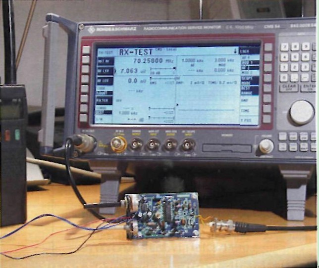
The CMS 54 has a plethora of other functions for some really gruelling tests on radio communications equipment and in particular PMRs. We hope to be able to use it again some time in the future.
Reprinted Url Of This Article: http://www.seekic.com/blog/project_solutions/2011/07/24/A_dipole_antenna_for_4_meters__(2).html
Print this Page | Comments | Reading(1433)
Article Categories
New published articles
· Imagination works with TSMC to develop FinFET process
Author:Ecco Reading(47912)
· XMOS pushes event-driven MCUs with lower price
Author:Ecco Reading(4201)
· Intel brings upgraded 32-nm SoC for smartphones
Author:Ecco Reading(3920)
· Micron pushes TLC 128-Gbit NAND flash
Author:Ecco Reading(4668)
· Intel will stop supplying desktop motherboards
Author:Ecco Reading(6009)
· Processor market was expected to regain strength in 2013
Author:Ecco Reading(4005)
· It was reported that TSMC sales fall steeply
Author:Ecco Reading(3675)
· Cisco, NXP work with auto wireless startup
Author:Ecco Reading(4339)
· Micron was impacted by manufacturing glitch
Author:Ecco Reading(4695)
· China can make 22-nm transistor by themselves
Author:Ecco Reading(4554)
· Chip market rebound is coming, according to survey
Author:Ecco Reading(4436)
· Sony, Toshiba will spend more on chips, iSuppli reports
Author:Ecco Reading(3999)
· Qualcomm becomes the 13th company to join NFC Forum board
Author:Ecco Reading(6853)
· TSMC increases building work for FinFET fab
Author:Ecco Reading(4515)
· TI plans to cut 1,700 jobs in OMAP shift
Author:Ecco Reading(5396)