

Project Solutions
Project C+ (1)
Published:2011/7/25 2:37:00 Author:Phyllis From:SeekIC
Data comms beyond light speed
Research papers by their nature are difficult for the average layman to understand. Here in the Elektor Electronics laboratory between the odd cup of coffee we spend much time studying scientific reports. A recent paper by a Japanese research group caught our eye because we were able to replicate the effects described using a very simple circuit and the results are so profound that it could change forever the way we send data.
The properties of light that most of you will be familiar with are that it travels in a straight line at a speed, c, of approximately 3 x 10s m/s. We should not forget to mention that this is only true when it is passing through a vacuum and not influenced by gravity. As soon as it enters another medium, light is slowed down and bent (refracted). In the latter part of 2003 M. D. Lukin and his colleagues at Harvard University announced in Nature [1] that they had successfully slowed down a pulse of light in a matrix of rubidium atoms such that it was stationary for a few hundred milliseconds before it was released and accelerated to regain light speed. The uses of this technology are manifold in the fields of quantum communications and photonics. Drawing on these techniques a team of Japanese researchers have adapted the technology (termed I-Ging) to accelerate precise (low frequency) pulses of electromagnetic energy along transmission lines to achieve incredible propagation speeds.
Inverting causality
The experimental set-up is shown in Figure 1. The pulse transmitter on the left of the diagram generates a signal pulse that is sent through the medium (either an optic fiber or simple cable) to the receiver circuit on the right hand side of the diagram. Two oscilloscopes are used to display the signal pulse when it is introduced to the medium and recovered by the receiver. The purpose of Project c+ is to demonstrate that by careful matching of the pulse to the fundamental characteristics of the transmission medium it is possible to achieve vastly reduced propagation delays. 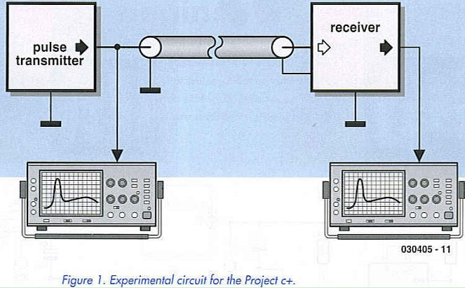
The breakthrough
It is often the case that a scientific breakthrough occurs by accident where unexpected or anomalous results suddenly cause the investigation to veer off in a totally different direction. The story of this breakthrough is a case in point, it seems as though during routine network testing one of the research team mistakenly entered a frequency range of MHz (yes, that’s millihertz) rather than MHz (megahertz) into a programmable waveform generator. The resultant effect on the test circuit was truly bizarre and may have easily been dismissed or overlooked had the researcher been less observant. Normally in the field of high speed communications we are accustomed to propagation delays in the order of picoseconds or even femtoseconds but provided we use the correctly profiled pulse shape (a fundamental I-Ging pulse containing no higher order harmonics) coupled to a transmission medium originally intended for much higher frequency signals it seems as though it is possible to accelerate the pulse to such an extent that it undergoes localised temporal inversion in its passage through the medium and arrives much earlier than predicted (hence c+).
The experimental circuit
The pulse generator in Figure 2 is quite straightforward and consists of a CMOS 555 timer IC together with two cascaded band-pass filters to produce the necessary pulse shape. The filter resistors are all 1% tolerance metal film types with a value of 1 Mfi (choose matched values where possible). Filter capacitors are low-loss foil types with 1% tolerance. The correct choice of components is critical to the success of the circuit, a fact to which any competent audio engineer will attest. 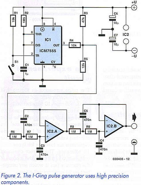
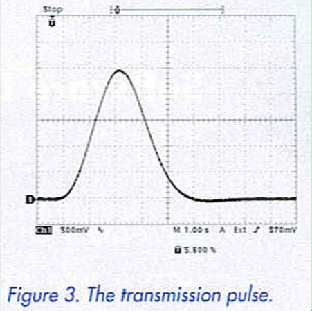
There are two possible power supply configurations for the circuit: either plus and minus 4.8 V consisting of eight NiMH AA type cells (if the TL082 op-amp is used) or a single-ended 4.8 V supply if a precision rail to rail op-amp like the OP290 is used. In this case the negative pole of the supply must be connected to the earth and all minus supply connections in the circuit diagram. To be scientifically rigorous the generator and receiver should be powered from separate power supplies to avoid cross coupling but a common supply will suffice for this experiment. Once the circuit is completed the output waveform of the I-Ging generator can be observed on an oscilloscope. When SI is pressed a transmission pulse similar to that shown in Figure 3 will be generated and sent down the medium. Each square graticule represents 1 second.
Reprinted Url Of This Article: http://www.seekic.com/blog/project_solutions/2011/07/25/Project_C___(1).html
Print this Page | Comments | Reading(996)
Article Categories
New published articles
· Imagination works with TSMC to develop FinFET process
Author:Ecco Reading(49315)
· XMOS pushes event-driven MCUs with lower price
Author:Ecco Reading(4247)
· Intel brings upgraded 32-nm SoC for smartphones
Author:Ecco Reading(3970)
· Micron pushes TLC 128-Gbit NAND flash
Author:Ecco Reading(4709)
· Intel will stop supplying desktop motherboards
Author:Ecco Reading(6048)
· Processor market was expected to regain strength in 2013
Author:Ecco Reading(4045)
· It was reported that TSMC sales fall steeply
Author:Ecco Reading(3715)
· Cisco, NXP work with auto wireless startup
Author:Ecco Reading(4378)
· Micron was impacted by manufacturing glitch
Author:Ecco Reading(4733)
· China can make 22-nm transistor by themselves
Author:Ecco Reading(4595)
· Chip market rebound is coming, according to survey
Author:Ecco Reading(4472)
· Sony, Toshiba will spend more on chips, iSuppli reports
Author:Ecco Reading(4033)
· Qualcomm becomes the 13th company to join NFC Forum board
Author:Ecco Reading(6894)
· TSMC increases building work for FinFET fab
Author:Ecco Reading(4557)
· TI plans to cut 1,700 jobs in OMAP shift
Author:Ecco Reading(5435)