

Project Solutions
Simple l2V to 230V Power Inverter--A mobile power outlet (2)
Published:2011/7/26 1:06:00 Author:Li xiao na From:SeekIC
Design by G. Gerards
Pulsewidth modulation
The central part in the circuit is an SG3526 low-cost switch-mode regulator, which is supplied by a number of manufacturers under the component identifier xx3526, where xx is a manufacturer-specific letter combination. The 3526 supports all known switch-mode PSU topologies. Its complete datasheets may be obtained free of charge from wwvj.unitrode.com (part search: UC3526 and Datasheet). 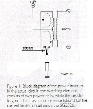
The basic operation of the power inverter is illustrated in Figure 1. The SG3526 alternately switches the current through the 12V windings of a mains transformer, the two central ends of the windings having been taken together and connected to the positive battery terminal (+12 V). At each switching action, the direction of the current changes and with it the direction of the magnetic field in the transformer core. The result is a square-wave(-like) alternating voltage at the 230-V side of the transformer.
In real life, the switch consists of two FETs in complementary arrangement (push-pull). The source connections of the FETs are taken to ground by way of very low resistances (compare the circuit diagram in Figure 3). 
The internal architecture of the SG3526 is shown in Figure 2. The input voltage +Vin may be between 7 V and 35 V, and is used to create a reference voltage Vggp of 5 V. A voltage guard blocks the drivers stages when the input voltage drops below 7 V. The drivers are separately powered via the +V0 connection. Using resistor RT and the capacitor at CT (again compare with circuit diagram in Figure 3) the frequency is determined, which is 50 Hz in this case. The resistor at RD causes a fixed dead time between the driver’s Output A and Output B. This is done to eliminate the risk of the two drivers (and consequently the two power FETs) conducting at the same time when the switch-over takes place. 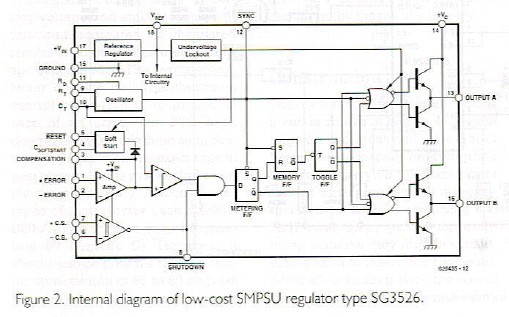
The capacitor at the CSOFTSTART P*11 (CSS, pin 4) allows the pulse mark/space (on/off) ratio of the outputs to be slowly raised to 48% after the supply voltage is switched on, or after a reset. The ’Amp’ voltage regulator is not used as such in our application; alternatively it takes the role of an impedance converter using the reference voltage as the controlling quantity. In this way it is assured that the outputs supply the full mark/space ratio after the start-up phase.
The current limiter using shunt resistor R8 triggers a shutdown sequence when the voltage between +CS and -CS (in other words, the drops across R8) exceeds 100 mV. However, the shutdown control may also be used externally by connecting it to ground. Because shutdown and Reset (pins 8 and 5 respectively) are interconnected in this circuit, the modulator starts again with a soft start after an overload condition or an external disconnect.
Reprinted Url Of This Article: http://www.seekic.com/blog/project_solutions/2011/07/26/Simple_l2V_to_230V_Power_Inverter__A_mobile_power_outlet_(2).html
Print this Page | Comments | Reading(6959)
Article Categories
New published articles
· Imagination works with TSMC to develop FinFET process
Author:Ecco Reading(30212)
· XMOS pushes event-driven MCUs with lower price
Author:Ecco Reading(3463)
· Intel brings upgraded 32-nm SoC for smartphones
Author:Ecco Reading(3183)
· Micron pushes TLC 128-Gbit NAND flash
Author:Ecco Reading(3664)
· Intel will stop supplying desktop motherboards
Author:Ecco Reading(5235)
· Processor market was expected to regain strength in 2013
Author:Ecco Reading(3249)
· It was reported that TSMC sales fall steeply
Author:Ecco Reading(3391)
· Cisco, NXP work with auto wireless startup
Author:Ecco Reading(3531)
· Micron was impacted by manufacturing glitch
Author:Ecco Reading(3937)
· China can make 22-nm transistor by themselves
Author:Ecco Reading(3709)
· Chip market rebound is coming, according to survey
Author:Ecco Reading(3678)
· Sony, Toshiba will spend more on chips, iSuppli reports
Author:Ecco Reading(3715)
· Qualcomm becomes the 13th company to join NFC Forum board
Author:Ecco Reading(6029)
· TSMC increases building work for FinFET fab
Author:Ecco Reading(3694)
· TI plans to cut 1,700 jobs in OMAP shift
Author:Ecco Reading(4480)