

Project Solutions
Simple l2V to 230V Power Inverter--A mobile power outlet(4)
Published:2011/7/26 20:43:00 Author:Li xiao na From:SeekIC
Design by G. Gerards
Construction
The design of the printed circuit board is shown in Figure 4. Despite large ground areas and wide tracks it may be necessary to strengthen the tracks carrying the transformer current by tinning them. It is recommended to start by mounting the AMP (’fast-on’) lugs (spade terminals), because they require considerable force to insert into the board. After all, a mishap with the use of pliers at this point could cause considerable damage to other components on the board. The wire link beside the shunt resistor R8 should not be forgotten. R8, by the way, should be mounted a little above the board surface to help it stay as cool as possible. If desired a higher-wattage resistor may be substituted (5 watts). Finally, do make sure you mount all polarised components (transistors, electrolytic capacitors, diodes and ICs) the right way around on the board. Insulating washers must be used when fitting the transistors onto the heatsink. 
Powering up
Commissioning this project only requires a multimeter. Initially, you use the inverter without the transformer connected. Connect it to an adjustable bench supply and check the two guard circuits: the voltage guard by adjusting the input voltage, and the temperature guard with the aid of your soldering iron, a potentiometer or any other means you see fit. In any case, the outputs will switch to ground and the LED will light when the voltage at the positive input of the comparators drops below that at the negative input. If the guard circuit appears to work, you proceed by measuring the two gate signals. If an error is present, both will read 0 V. In the case of an error-free circuit, an oscilloscope will show two clean rectangular-wave signals with 10-ms long pulses. Using your multimeter, the same measurement yields a readout of about half the supply voltage.
All approved so far, you are in a position to connect the toroidal transformer. At this point, it makes sense to remove IC1 from its socket, as in that case the shutdown can only be triggered by the current limiter. If an ordinary 100-watt bulb does not light up within a few seconds, measure the voltage at the shutdown control (pin 8 on the 3526 or the anode of D2). If you measure less than 5 V, the current limiter or the soft-start time has to be tweaked as described above.
Once the bulb lights, you may (carefully!) check if the inverter is short-circuit resistant. If an oscilloscope is available, the FET current may be measured (= the voltage across R8) and use R16 to increase the current limit point to about 201S below the permissible drain current. This is of course done with the 230-Vac output short-circuited.
It is normal for the transformer to make more noise under no-load conditions than you would expect when in normal use. This is caused by the rectangular wave switching the magnetic field hard and fast. Core saturation under no-load conditions is signalled by ugly sounds from the transformer. Measured with an oscilloscope the currents will not rise in sawtooth-wise but with peaks (overshoot). In that case, the 12-V windings on the transformer require just a few more turns. If that is problematic, the alternative is to raise the oscillator frequency a little by using a slightly lower value for Rll. The resulting output frequency may well be 55 Hz, but that is immaterial for most loads and the circuit is not suitable anyway to power an alarm clock.
Practical results
Because a voltage regulation loop omitted for the sake of simplicity and cost, the output voltage is dependent on the battery voltage. The output voltage of the author’s prototype loaded with a 150-watt halogen lamp is shown in Table 1, as a function of battery voltage. 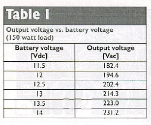
The output voltage is dependent on the transformer’s winding ratio and output current. If you want to reach the nominal output voltage of 230 Vac at 13 Vdc input, you should consider using a transformer with two 11-volt windings. On the prototype, a maximum efficiency of 94% was measured and the circuit was found to be Dirk-proof.
Reprinted Url Of This Article: http://www.seekic.com/blog/project_solutions/2011/07/26/Simple_l2V_to_230V_Power_Inverter__A_mobile_power_outlet(4).html
Print this Page | Comments | Reading(1047)
Article Categories
New published articles
· Imagination works with TSMC to develop FinFET process
Author:Ecco Reading(30163)
· XMOS pushes event-driven MCUs with lower price
Author:Ecco Reading(3460)
· Intel brings upgraded 32-nm SoC for smartphones
Author:Ecco Reading(3180)
· Micron pushes TLC 128-Gbit NAND flash
Author:Ecco Reading(3660)
· Intel will stop supplying desktop motherboards
Author:Ecco Reading(5230)
· Processor market was expected to regain strength in 2013
Author:Ecco Reading(3247)
· It was reported that TSMC sales fall steeply
Author:Ecco Reading(3389)
· Cisco, NXP work with auto wireless startup
Author:Ecco Reading(3529)
· Micron was impacted by manufacturing glitch
Author:Ecco Reading(3934)
· China can make 22-nm transistor by themselves
Author:Ecco Reading(3706)
· Chip market rebound is coming, according to survey
Author:Ecco Reading(3676)
· Sony, Toshiba will spend more on chips, iSuppli reports
Author:Ecco Reading(3713)
· Qualcomm becomes the 13th company to join NFC Forum board
Author:Ecco Reading(6027)
· TSMC increases building work for FinFET fab
Author:Ecco Reading(3691)
· TI plans to cut 1,700 jobs in OMAP shift
Author:Ecco Reading(4477)