

Project Solutions
Pocket Pong: a primeval game cast in modern hardware (1)
Published:2011/8/5 1:18:00 Author:Li xiao na From:SeekIC
By Andy Morell
Provided they manage to recognize them in the first place, youngsters will label classics like Pacman and Pong as video games although historically they are ’video games’, the concept behind them dating back to the 1950’s. In this article you’ll find a modern (computer) version of such a prehistoric game that — as far as we are concerned — has not lost any of its compulsive character.
It is easily forgotten that the first electronic games were played on a TV set. In fact, technology at the time nearly did not make it to TV altogether. In 1951, TV technician Ralph Baer thought it would be nice to use the telly as a screen for an electronic game. His boss however did not see the promise and the idea was quickly abandoned. Years later, however, it started to surface again and in 1966 Baer started to build one of his early prototypes. The video game was born. The game covered by this article is Atari’s ’Pong’ which is actually a derivate of one of Baer’s original concepts. The first versions for use at home were designed around 1974. As opposed to other manufacturers, Atari found the pot of gold: an ASIC (application specific integrated circuit) was designed for Pong. The chip allowed the production costs to be kept low while the game functionality (including a digital on-screen scoreboard and sound effects) was excellent compared to competitive products. The home version of Pong was launched in 1976. Today, 28 years later, we have another go at casting Pong in electronics. This time, we will not be using a TV set for the ’screen’ but a LED matrix.
The circuit
Just like Atari did many years ago, we will be designing a chip tailored to the game only. Fortunately, that no longer means you have to design a completely new circuit and burn it into a chip. Today we simply use a microcontroller running software that tells it exactly what to do. We chose the PIC18F452, a 40-pin MCU containing, among others, 32 kBytes of program memory and a 10-bit A-D converter. As you can see from Figure 1, the PIC is not the only IC in the circuit. IC2, a 4-to-16 line decoder, together with IC3 and IC4 arranges the display control. The display actually consists of two parts: the 7-segment displays LD1 and LD2 showing the ’score’ and a LED matrix (D1-D88) that mimics the playng field. Virtual rackets or bats move at the left and right side of the court, allowing the ball to be bounced back and forth. 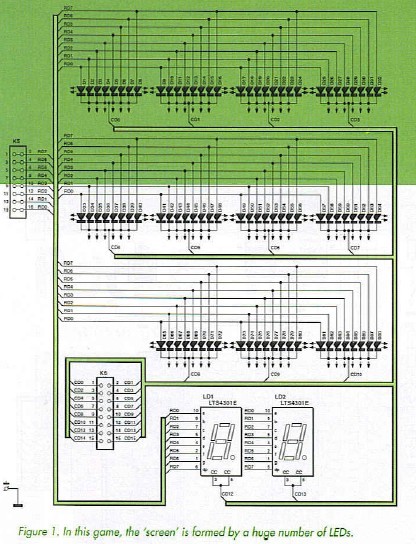
Buzzer Bzl provides the sound effects. You are looking at a dc (or ’active’) piezo buzzer that’s driven by transistor Tl. C5 and R7 afford sufficient decoupling of the supply voltage. The power supply around IC5 is dead standard. Diode D89 affords a degree of protection against an accidentally reverse polarized mains adapter (with 9-12 VDC output). With the PIC drawing just a few milliamps, it is fair to say that the current consumption of our electronic game goes on account on the LEDs. However, thanks to the multiplexed drive scheme used here, the average current consumption remains limited to a modest 35 mA or so.
Display
Both the LEDs in the 7-segment displays and the LEDs in the matrix have their cathodes connected via ULN2803 driver ICs (IC3 and IC4). The anodes are connecting to the MCU port lines via transistors T2-T9. It would appear that the transistors are not strictly necessary as the PIC port lines are specified at 25 mA each. This may well be sufficient for high-efficiency LEDs. but it isn’t with regular LEDs which at such a low current light dimly, reducing the playability’ of the game.
Using the indicated component values (i.e. with transistors and R8-R15 = 56 ohm) a LED current of about 27 mA is obtained. By the way, the value of R8-R15 may be changed without problems using Ohm’s law. Assume a supply voltage of 5 V, then subtract the following: collector-emitter drop (0.7 V); LED ’on’ voltage (approx. 1.8 V for red LEDs); voltage drop across Darlington drivers in the ULN2803 (approx. 1 V). That leaves about 1.5 V across the resistor. If the desired current is 10 mA, V = I x R tells you that 1.5 = 0.01 x R, or 1.5 / 0.01 = 150 ohms.
Reprinted Url Of This Article: http://www.seekic.com/blog/project_solutions/2011/08/05/Pocket_Pong__a_primeval_game_cast_in_modern_hardware_(1).html
Print this Page | Comments | Reading(341)
Article Categories
New published articles
· Imagination works with TSMC to develop FinFET process
Author:Ecco Reading(30195)
· XMOS pushes event-driven MCUs with lower price
Author:Ecco Reading(3462)
· Intel brings upgraded 32-nm SoC for smartphones
Author:Ecco Reading(3182)
· Micron pushes TLC 128-Gbit NAND flash
Author:Ecco Reading(3662)
· Intel will stop supplying desktop motherboards
Author:Ecco Reading(5233)
· Processor market was expected to regain strength in 2013
Author:Ecco Reading(3249)
· It was reported that TSMC sales fall steeply
Author:Ecco Reading(3390)
· Cisco, NXP work with auto wireless startup
Author:Ecco Reading(3530)
· Micron was impacted by manufacturing glitch
Author:Ecco Reading(3936)
· China can make 22-nm transistor by themselves
Author:Ecco Reading(3708)
· Chip market rebound is coming, according to survey
Author:Ecco Reading(3678)
· Sony, Toshiba will spend more on chips, iSuppli reports
Author:Ecco Reading(3715)
· Qualcomm becomes the 13th company to join NFC Forum board
Author:Ecco Reading(6028)
· TSMC increases building work for FinFET fab
Author:Ecco Reading(3693)
· TI plans to cut 1,700 jobs in OMAP shift
Author:Ecco Reading(4479)