

Project Solutions
Four in a Row: Play against each other or against the micro! 3
Published:2011/8/7 22:41:00 Author:Amy From:SeekIC
By Steve Teal
Construction
You should choose a suitable case before starting with the construction of the PCB. We’ve chosen a Pactec case without a battery compartment. The bare PCB can then be used as a drill template. We have added some extra holes for this in the centre of the switches. Try to keep the height of the populated PCB as low as possible. The LEDs and switches should rise above all other components. Keep this in mind when you buy the components and mount the electrolytic capacitors horizontally if necessary (first measure the available space in the case).
You can also gain some space by avoiding IC sockets. If you find this a bit scary, you should consider the method we’ve used in our prototype (Figure 3). This is covered in more detail in one of the design tips elsewhere in this issue. 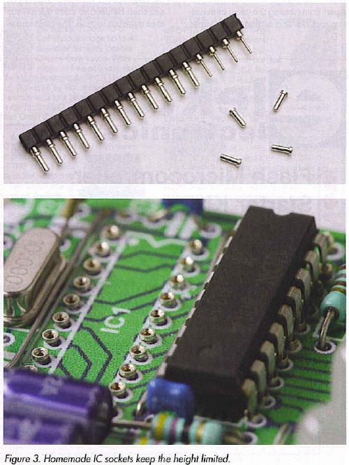
As always, you should start with the wire links on the PCB. You should then solder the rest of the components, but leave the LEDs till last. Check the polarity and make sure that they are all at the same height above the PCB.
The microcontroller can be programmed in advance or via connector PL1.
There may be some unusual behavior during testing. Especially when a 6 V supply with diode (instead of 9 V and a voltage regulator) is used, you’ll find that the voltage on the PCB drops very slowly after the battery is disconnected, due to the very low current consumption. One consequence of this is that the voltage doesn’t drop far enough for the power-up reset to work when the battery is reconnected. This makes it appear as if the circuit is no longer working, even though power is applied. If this happens you could reset the processor manually by briefly shorting C6.
Playing a game
When power is first applied a diagonal line of burning LEDs moves across the play area. The default setting is for one player to play against the microcontroller.
When one of the switches underneath a column is pressed, a dropping disc is simulated. Next it is the micro’s turn and after about a second it will make its move using the other colour.
Then it is the first player’s turn again and this continues until one of the players has ’four in a row’ (horizontally, vertically or diagonally), or until the board is full. Flashing LEDs shows a winning line. This is shown for about 12 seconds, after which a diagonal line of LEDs clears the board and a new game can be started.
When the playing field is completely full, without there being a winner, it becomes a draw. The game will stay in this state until a new game is started or the last move is undone.
If no switch is pressed for about a minute, the processor turns itself off. The shift key (SI) should then be used to turn the game on again. The game then carries on from where it left off previously. Should there be no active game in the memory the diagonal line moves across the board, indicating the start of a new game.
Reprinted Url Of This Article: http://www.seekic.com/blog/project_solutions/2011/08/07/Four_in_a_Row__Play_against_each_other_or_against_the_micro_3.html
Print this Page | Comments | Reading(338)
Article Categories
New published articles
· Imagination works with TSMC to develop FinFET process
Author:Ecco Reading(30204)
· XMOS pushes event-driven MCUs with lower price
Author:Ecco Reading(3463)
· Intel brings upgraded 32-nm SoC for smartphones
Author:Ecco Reading(3183)
· Micron pushes TLC 128-Gbit NAND flash
Author:Ecco Reading(3662)
· Intel will stop supplying desktop motherboards
Author:Ecco Reading(5234)
· Processor market was expected to regain strength in 2013
Author:Ecco Reading(3249)
· It was reported that TSMC sales fall steeply
Author:Ecco Reading(3390)
· Cisco, NXP work with auto wireless startup
Author:Ecco Reading(3531)
· Micron was impacted by manufacturing glitch
Author:Ecco Reading(3937)
· China can make 22-nm transistor by themselves
Author:Ecco Reading(3709)
· Chip market rebound is coming, according to survey
Author:Ecco Reading(3678)
· Sony, Toshiba will spend more on chips, iSuppli reports
Author:Ecco Reading(3715)
· Qualcomm becomes the 13th company to join NFC Forum board
Author:Ecco Reading(6029)
· TSMC increases building work for FinFET fab
Author:Ecco Reading(3694)
· TI plans to cut 1,700 jobs in OMAP shift
Author:Ecco Reading(4480)