

Project Solutions
Vehicle Battery Jogger-keep your battery fresh and young (2)
Published:2011/8/7 22:48:00 Author:Phyllis From:SeekIC
By Karel Walraven
Operation
The first 555 timer (IC1 in Figure 1) operates as an astable multivibrator and generates a continuous stream of pulses. The second 555 is a monostable multivibrator that is triggered on each negative edge of the pulses coming from its companion. As a result, it generates short pulses that drive power FET Tl fully on. The FET connects the battery directly to a power resistor, causing a heavy current to flow. The size of this current is primarily determined by the value of resistor R8. 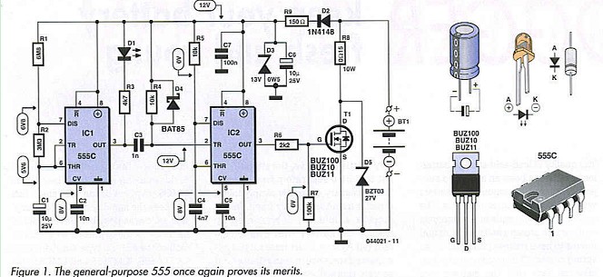
The FET is intentionally driven here via a gate stopper resistor with a relatively high value. This causes it to switch on and off somewhat more slowly, which reduces the amount of interference generated. In this case, ’slow’ means a few microseconds; a FET that’s driven hard switches within a few nanoseconds. Here it isn’t necessary to switch quickly, and there’s no need to be concerned about a bit of extra power dissipation. Despite the relatively slow switching, rather large voltage spikes can occur when the FET switches off. It is thus essential to connect a fast Zener diode (D5) across the FET for protection.
Construction
It’s important to ensure that the ICs and IC sockets are fitted with the correct orientation. The sockets usually have a notched or bevelled comer, and the ICs have a dimple in the package. As seen from above, the topmost pin to the left of this marking is pin 1. It’s best to use CMOS versions of the ICs, since this will keep the standby current consumption as low as possible. Several different manufacturers make the CMOS version of the 555, so type numbers such as TLC555, ICM7555 and LMC555 (as well as many others) all refer to the same kind of IC. However, the NE555, SE555 and LM555 are not CMOS types. They can also be used, but the current consumption will then be quite a bit higher (more than 10 mA).
Most of the current is actually used by the LED, so you should use a low-current type here (also referred to as a ’2-mA LED’). When fitting it to the circuit board, make sure the long lead goes next to the triangle marking.
The capacitors in the circuit (except for the electrolytic capacitors) are ceramic types. That’s because component value tolerance is not terribly important in this case, and a bit of temperature dependence also doesn’t particularly matter.
New electrolytic capacitors also have one lead that’s longer than the other one. That’s usually the positive lead. On the circuit board, it must be placed next to the open rectangle. There’s usually also a white stripe with minus (-) signs printed on the case of the capacitor. This marks the negative lead, which is indicated on the circuit board by a solid rectangle (the open rectangle is the + terminal).
Reprinted Url Of This Article: http://www.seekic.com/blog/project_solutions/2011/08/07/Vehicle_Battery_Jogger_keep_your_battery_fresh_and_young__(2).html
Print this Page | Comments | Reading(1544)
Article Categories
New published articles
· Imagination works with TSMC to develop FinFET process
Author:Ecco Reading(30204)
· XMOS pushes event-driven MCUs with lower price
Author:Ecco Reading(3463)
· Intel brings upgraded 32-nm SoC for smartphones
Author:Ecco Reading(3183)
· Micron pushes TLC 128-Gbit NAND flash
Author:Ecco Reading(3662)
· Intel will stop supplying desktop motherboards
Author:Ecco Reading(5234)
· Processor market was expected to regain strength in 2013
Author:Ecco Reading(3249)
· It was reported that TSMC sales fall steeply
Author:Ecco Reading(3391)
· Cisco, NXP work with auto wireless startup
Author:Ecco Reading(3531)
· Micron was impacted by manufacturing glitch
Author:Ecco Reading(3937)
· China can make 22-nm transistor by themselves
Author:Ecco Reading(3709)
· Chip market rebound is coming, according to survey
Author:Ecco Reading(3678)
· Sony, Toshiba will spend more on chips, iSuppli reports
Author:Ecco Reading(3715)
· Qualcomm becomes the 13th company to join NFC Forum board
Author:Ecco Reading(6029)
· TSMC increases building work for FinFET fab
Author:Ecco Reading(3694)
· TI plans to cut 1,700 jobs in OMAP shift
Author:Ecco Reading(4480)