

Project Solutions
Personal Sound to Light Unit: small but sophisticated (1)
Published:2011/8/8 0:48:00 Author:Li xiao na From:SeekIC
By Burkhard Kainka
Disco nights are great fun from time to time but you don’t want to overdo it in regard of the sound volumes you’re exposed to for a couple of hours. Arguably there’s no less pleasure in enjoying dance music in the privacy of your home, study or student bigs. However, the true disco feeling is not obtained without a matching sound to light unit, so here’s a really small version.
A sound to light unit converts music signals into light pulses. In most cases, three channels are used to cover different frequency ranges. The bass channel will then indicate the ’beat’ of the music by a more or less rhythmical flash, while the two other channels represent the higher frequency ranges of the music channel.
The ’private’ version of a sound to light unit discussed in this article employs three coloured LEDs instead of powerful flashing lights or floodlights as used in most discos. For the rest, it has practically the same functionality as the ’real thing’ experienced on Saturday nights. However, a direct connection to the music amplifier is not necessary as the unit we’ve in mind has been designed to pick up the sound information through a microphone. Another peculiarity of the circuit is the automatic sensitivity adaptation to the music volume detected. In this way the circuit can work without any controls.
The circuit draws an average current of just 20 mA and works happily off a 9-volt PP3 block battery. However, the low current requires super bright LEDs to be used to ensure sufficient brightness.
Amplify it 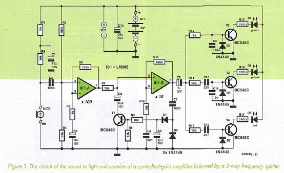
High amplification is required to enable the tiny signals produced by an electret microphone to be turned into bright flashes from LEDs. The circuit diagram in Figure 1 shows that we employ two operational amplifiers with a total gain of about 1000 times. The input of the first opamp (IC1.A) is connected to the electret microphone capsule via coupling capacitor C2. The microphone is given a certain DC bias level obtained from the 9-V supply rail by resistors Rl and R2. Rl together with electrolytic capacitor CI decouple the supply voltage for the sensitive microphone while R2 equals the microphone impedance. Capacitor C2, then, ensures that the microphone bias level does not appear at the opamp input. In other words, it will only pass the alternating component, which is caused by sound picked up by the microphone. The + input of the opamp has its own bias voltage supplied by potential divider R3-R4. Because the two resistors have the same value, the supply voltage is effectively halved, i.e., 4.5 V exists at the junction of R3 and R4 (assuming a nominal 9 V supply). This bias voltage will also exist at the output of the first opamp and, because of R7, at the input of the second one (IC1.B) whose output will also copy this dc level. In this way, R3 and R4 keep both opamps biased at half the supply voltage. Both opamps are used in the non-inverting configuration hence provide unity (1) dc gain. For alternating signals, however, the gain is much greater In the case of the first opamp, the gain is determined by the ratio between resistors R6 and R5, or R11/R10 for the second opamp. Just look at the relevant resistor values and you’ll discover that IC1A is configured for a gain of 100 and IC1.B for a gain of 10.
The signal level at the output of IC1.B is rectified by Dl and D2, smoothed by C6 and then used to drive n-p-n transistor Tl. To the signal voltage at the output of IC1.A, the combination of R7 and Tl looks like a voltage divider. With rising signal levels, the rectified voltage on C6 also rises and the transistor is driven harder because of the larger base current supplied by R9. The result is a lower resistance in the transistor and consequently a lower AF signal behind R7.
You may wonder why we did not use an n-p-n transistor without direct current in the collector circuit. Alternatively you might have expected to see a FET at this position, its drain-source junction acting as a controlled resistance. It is less known that virtually the same function may be obtained from a regular switching/AF transistor like the ubiquitous BC548C. An n-p-n transistor, too, represents a variable resistance that can be controlled within a certain range. However, for a low-distortion volume control, only a tiny signal level (of the order of millivolts) may be applied to the collector. This condition is not satisfied here as the output voltage is regulated to about 1 Vpp. If the second stage has a gain of 10, about 100 mVDD can be found at the collector. At such a level, distortion occurs that will not be acceptable in other applications. No problem for the sound to light unit, however, because the output signal is used to control LEDs than drive an audio amplifier. If you do want to use such a ’volume control’ for audio applications, you should make sure a much smaller signal level is handled, which is probably easiest realized by moving the automatic volume control towards the circuit input.
Reprinted Url Of This Article: http://www.seekic.com/blog/project_solutions/2011/08/08/Personal_Sound_to_Light_Unit__small_but_sophisticated_(1).html
Print this Page | Comments | Reading(1933)
Article Categories
New published articles
· Imagination works with TSMC to develop FinFET process
Author:Ecco Reading(30171)
· XMOS pushes event-driven MCUs with lower price
Author:Ecco Reading(3461)
· Intel brings upgraded 32-nm SoC for smartphones
Author:Ecco Reading(3181)
· Micron pushes TLC 128-Gbit NAND flash
Author:Ecco Reading(3661)
· Intel will stop supplying desktop motherboards
Author:Ecco Reading(5231)
· Processor market was expected to regain strength in 2013
Author:Ecco Reading(3248)
· It was reported that TSMC sales fall steeply
Author:Ecco Reading(3390)
· Cisco, NXP work with auto wireless startup
Author:Ecco Reading(3530)
· Micron was impacted by manufacturing glitch
Author:Ecco Reading(3935)
· China can make 22-nm transistor by themselves
Author:Ecco Reading(3707)
· Chip market rebound is coming, according to survey
Author:Ecco Reading(3677)
· Sony, Toshiba will spend more on chips, iSuppli reports
Author:Ecco Reading(3714)
· Qualcomm becomes the 13th company to join NFC Forum board
Author:Ecco Reading(6028)
· TSMC increases building work for FinFET fab
Author:Ecco Reading(3692)
· TI plans to cut 1,700 jobs in OMAP shift
Author:Ecco Reading(4478)