

Project Solutions
Personal Sound to Light Unit: small but sophisticated (2)
Published:2011/8/8 1:04:00 Author:Li xiao na From:SeekIC
By Burkhard Kainka
Filter
The output signal supplied by the second opamp drives the LED controls by way of simple filters. Each LED driver stage consists of a transistor (T2, T3 and T4). To prevent the transistor bases from being charged with negative levels, anti-parallel diodes (D3, D5, D7) are used on each base terminal. Each transistor is only actuated on the positive half cycle of the drive voltage. Overall, however, the higher frequencies do cause an impression of average brightness.
The filters consist of simple RC networks broadly dimensioned for a cutoff frequency using the formula
fc = 1 / (2πR C) |Hz|
For example, the low-pass section R12/C9 is dimensioned for about 160 Hz using 10 kΩ (R12) and 100 nF (C9). All lower frequencies in the music signal will therefore pass through this ’channel’ The mid-tone channels contains a combined high-pass / low-pass filter R14/C10+C11. The treble channel is driven by a simple high-pass R16/C12. If necessary the cut-off frequencies may be changed to suit individual requirements and that’s easiest done by making small changes to the capacitor values.
Printed circuit board 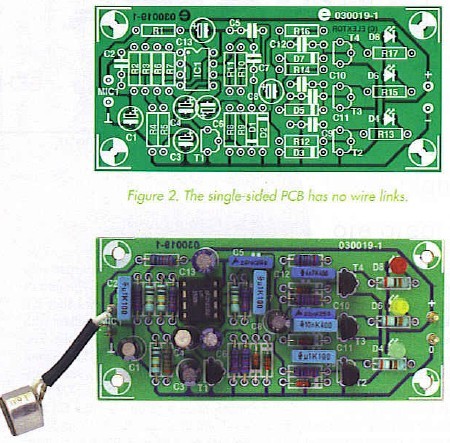
If the circuit of a relatively simple design, the actual construction of the sound to light unit is made even simpler by a printed circuit board (Figure 2). The two opamps we’ve discussed are contained in a single IC type LM385, which is best fitted in an IC socket (look at the notch in the IC body). The single-sided PCB has no wire links. No problems are expected to arise if you watch the polarity of the diodes, electrolytic capacitors and LEDs and work carefully all the way. The electret (or ’condenser’) microphone insert can be almost any available type as long as it has two terminals.
The maximum LED current amounts to about 18 mA so the circuit is suitable for LEDs described as ’standard’, ’bright’ and ’superbright’. Using the latter the effect of the 3-way filtering is more pronounced; while for a relatively small room with not too much light ordinary LEDs will be found to be perfectly suitable. If you decide to use low-current LEDs, the value of series resistors R13, R15 and R17 should be increased to 3.3 k or even 3.9 k. The resulting reduction in current consumption will enable your 9-V battery to last much longer.
Reprinted Url Of This Article: http://www.seekic.com/blog/project_solutions/2011/08/08/Personal_Sound_to_Light_Unit__small_but_sophisticated_(2).html
Print this Page | Comments | Reading(1113)
Article Categories
New published articles
· Imagination works with TSMC to develop FinFET process
Author:Ecco Reading(30190)
· XMOS pushes event-driven MCUs with lower price
Author:Ecco Reading(3461)
· Intel brings upgraded 32-nm SoC for smartphones
Author:Ecco Reading(3181)
· Micron pushes TLC 128-Gbit NAND flash
Author:Ecco Reading(3662)
· Intel will stop supplying desktop motherboards
Author:Ecco Reading(5231)
· Processor market was expected to regain strength in 2013
Author:Ecco Reading(3248)
· It was reported that TSMC sales fall steeply
Author:Ecco Reading(3390)
· Cisco, NXP work with auto wireless startup
Author:Ecco Reading(3530)
· Micron was impacted by manufacturing glitch
Author:Ecco Reading(3935)
· China can make 22-nm transistor by themselves
Author:Ecco Reading(3707)
· Chip market rebound is coming, according to survey
Author:Ecco Reading(3677)
· Sony, Toshiba will spend more on chips, iSuppli reports
Author:Ecco Reading(3714)
· Qualcomm becomes the 13th company to join NFC Forum board
Author:Ecco Reading(6028)
· TSMC increases building work for FinFET fab
Author:Ecco Reading(3692)
· TI plans to cut 1,700 jobs in OMAP shift
Author:Ecco Reading(4478)