

Project Solutions
Rail Router: model train routing with a PC (1)
Published:2011/8/8 2:17:00 Author:Li xiao na From:SeekIC
By Ray King
"Smooth Operator" elsewhere in this issue employs model control servos to drive the turnouts on a model railway. One of its advantages is that it can be activated over a single wire making it ideal for computer control described...here! Rail router is a hardware/software combination capable of controlling up to 127 turnouts.
The Rail Router hardware comes in two flavors: a master router board capable of directly controlling up to 15 devices and a slave board connected up via a ribbon cable and adding a further 16 turnout controls. The general layout of the system is illustrated in Figure 1. The master and slave circuits use the same printed circuit board stuffed to reflect the desired function. Slave routers are optional — if you are satisfied with ’just’ 15 turnouts and/or semaphores then you’re fine with just the master router. 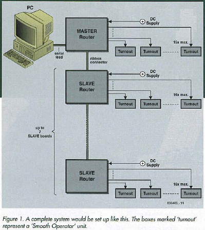
A dual-purpose circuit.... 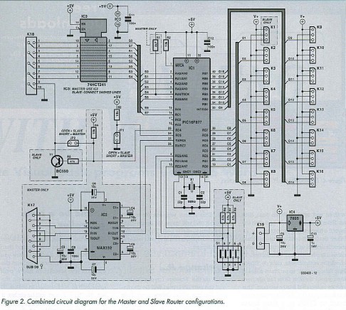
The circuit diagram shown in Figure 2 is unusual in that it shows the master as well as the slave circuit. Dashed outlines and connections are used to indicate the difference between the two circuits, which can be built on one and the same board. Electrically the difference between the two circuits exists in the presence or absence of jumpers and circuit parts. The MAX232 two-way RS232/TTL level converter, for example, is only required for the master function, which (as you may have guessed already) requires a connection with a PC running the specially written Rail Router control software (more about this further on). The RS232 port on the PC is connected up to the Rail Router master board via sub-D socket K17. Only Tx/Rx traffic is used, without handshaking.
A PIC16F877 microcontroller is found at the heart of the master as well as the slave circuit. Although the micro is loaded with the one that the same software for the master or slave function, it actually selects between two different code chunks by looking at the logic level you’ve defined at port line RC5 by means of jumper JP1. The 16F877 ticks at 8 MHz as determined by quartz crystal XI and its loading capacitors CI and C2. The master and slave router boards require a power supply of 8 V to 15 V DC which can be provided by a small mains adaptor or from a DC outlet on one of the railway speed governors.
Master operation
The PIC micro continuously monitors the incoming serial information, determining whether the device specified in the command is comprised in the first 15 turnouts. If so, it changes the state of the turnout control (via K2-K16). If not, it passes the information over to buffer IC3 and from there to connector K18 for slave units to test. Each output connector (K1-K16) on the router board comprises an unregulated supply (V+) ground and the control lead as required by the ’Smooth Operator’ servo control circuits. Note that Output #1 (Kl) is not used by the master configuration. It is planned to employ it at a later stage for enhanced facilities.
Slave operation
The operation of the slave board is similar to that of the master but simpler because of the absence of the RX/TX serial interface with the PC. The unique address of each slave board is determined by the settings of DIP switch SI. Setting the address to 001, for example, allows the slave board to operate turnouts 16 through 31, where code 001 is RE2 = 0; RE1 =0andRE0= Ion the PIC.
Reprinted Url Of This Article: http://www.seekic.com/blog/project_solutions/2011/08/08/Rail_Router__model_train_routing_with_a_PC_(1).html
Print this Page | Comments | Reading(2251)
Article Categories
New published articles
· Imagination works with TSMC to develop FinFET process
Author:Ecco Reading(30176)
· XMOS pushes event-driven MCUs with lower price
Author:Ecco Reading(3461)
· Intel brings upgraded 32-nm SoC for smartphones
Author:Ecco Reading(3181)
· Micron pushes TLC 128-Gbit NAND flash
Author:Ecco Reading(3661)
· Intel will stop supplying desktop motherboards
Author:Ecco Reading(5231)
· Processor market was expected to regain strength in 2013
Author:Ecco Reading(3248)
· It was reported that TSMC sales fall steeply
Author:Ecco Reading(3390)
· Cisco, NXP work with auto wireless startup
Author:Ecco Reading(3530)
· Micron was impacted by manufacturing glitch
Author:Ecco Reading(3935)
· China can make 22-nm transistor by themselves
Author:Ecco Reading(3707)
· Chip market rebound is coming, according to survey
Author:Ecco Reading(3677)
· Sony, Toshiba will spend more on chips, iSuppli reports
Author:Ecco Reading(3714)
· Qualcomm becomes the 13th company to join NFC Forum board
Author:Ecco Reading(6028)
· TSMC increases building work for FinFET fab
Author:Ecco Reading(3692)
· TI plans to cut 1,700 jobs in OMAP shift
Author:Ecco Reading(4478)