

Project Solutions
NOISE SUPPRESSION FILTERS - For ClariTy and other final amps (3)
Published:2011/8/10 21:47:00 Author:Phyllis From:SeekIC
By Ton Giesberts
The filter also contains two robust varistors that provide additional protection against sporadic mains disturbances (transients), although they don’t protect against common-mode transients.
Rl and R2 ensure that the capacitors are quickly discharged if no mains voltage is present (and after it’s disconnected). This prevents dangerous voltages from remaining present on the mains connector. For safety, use plastic stand-off bushes for mounting the circuit board in order to maintain adequate clearance between the circuit board tracks and protruding connections on the copper side and the metal parts of the enclosure. For a Class-1 device, a separation of 3 mm is in principle sufficient, but 6 mm is recommended.
As the inductor is attached to the circuit board quite securely by its four leads, additional mechanical fastening is not required. For anyone who nevertheless considers mechanical fastening necessary, a hole is provided in the circuit board in the middle of the inductor. Be sure to use only plastic parts for any such fastening, in order to avoid affecting the inductance of the coils. The layout of the printed circuit board is shown in Figure 3. 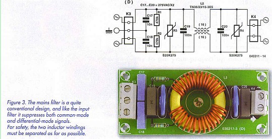
Capacitors C19 and C20 form part of the differential-mode suppression network, but given the low impedance of the power supply and mains network, they have less effect than C17 and C18, which provide common-mode suppression. These two capacitors are configured in parallel for common-mode signals, so they constitute a 20-nF capacitor that forms an LC filter in combination with the self-inductance of L5.
The impedance of the amplifier for common-mode signals primarily depends on the parasitic capacitance between the primary and secondary windings of the supply transformer (as well as the impedance of the wiring inside the enclosure), and it is reasonably high. This means that the self-inductance of the inductor is primarily responsible for filtering common-mode signals.
The values of C17 and C18 cannot easily be increased, since they also generate leakage currents to ground when the filter is connected to the mains voltage (via one of the two capacitors, depending on which one is connected to the live mains lead).
The ground rail of the filter is connected to the enclosure together with the ground connection of the mains inlet connector.
Speaker filter
In contrast to the mains filter, the inductors for the loudspeaker filters (Figure 4) are would bifilar (see Figure 5). Consequently you have to wind two lengths of 1.5-mm copper wire on the core at the same time, which takes even more strength. 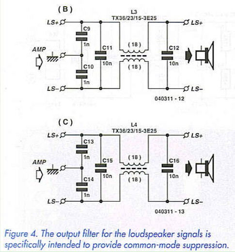
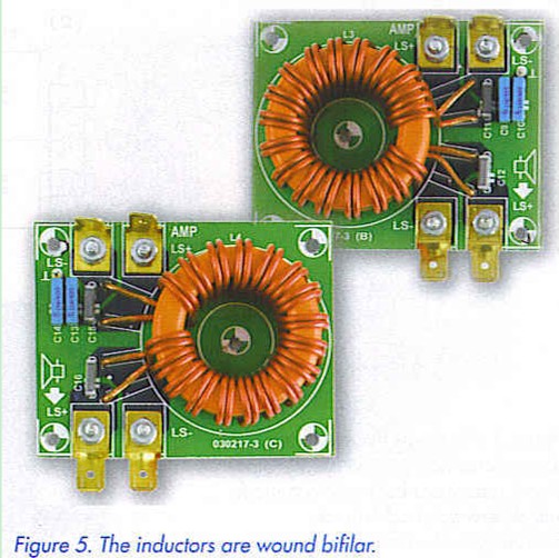
Bifilar winding ensures excellent coupling between the two windings and causes the leakage inductance to be very small. You have to bear in mind that peak currents of around 20 A can flow through the wires of the inductor. If the windings are not identical, the inductor will saturate and the filter will be ineffective.
Naturally, using these filters slightly increases the output impedance of the amplifier. Flat tab connectors are used for the connections, due to the potentially high currents. This also makes it possible to connect leads directly to the circuit board using M3 solder lugs (spade terminals). This helps avoid a certain amount of contact resistance. Another possibility is to solder the leads directly to the copper side.
Here we selected 3E25 core material. It has somewhat lower permeability than 3E5 material, but it can be used over a wider frequency range and is less prone to saturation (although that isn’t so important if the inductor is wound properly). The selected core has the same dimensions as the one used in the mains filter.
As no special insulation between the two windings is necessary here (although the copper wires must naturally have a heavy enamel coating), it’s easily possible to add two more turns. The two 18-tura windings of 1.5-mm enamelled copper wire yield an inductor with a self-inductance of approximately 2 x 2.4 mH ±25 % and a leakage inductance of only 2 uH.
Reprinted Url Of This Article: http://www.seekic.com/blog/project_solutions/2011/08/10/NOISE_SUPPRESSION_FILTERS___For_ClariTy_and_other_final_amps__(3).html
Print this Page | Comments | Reading(4621)
Article Categories
New published articles
· Imagination works with TSMC to develop FinFET process
Author:Ecco Reading(30163)
· XMOS pushes event-driven MCUs with lower price
Author:Ecco Reading(3460)
· Intel brings upgraded 32-nm SoC for smartphones
Author:Ecco Reading(3180)
· Micron pushes TLC 128-Gbit NAND flash
Author:Ecco Reading(3660)
· Intel will stop supplying desktop motherboards
Author:Ecco Reading(5230)
· Processor market was expected to regain strength in 2013
Author:Ecco Reading(3247)
· It was reported that TSMC sales fall steeply
Author:Ecco Reading(3389)
· Cisco, NXP work with auto wireless startup
Author:Ecco Reading(3529)
· Micron was impacted by manufacturing glitch
Author:Ecco Reading(3934)
· China can make 22-nm transistor by themselves
Author:Ecco Reading(3706)
· Chip market rebound is coming, according to survey
Author:Ecco Reading(3676)
· Sony, Toshiba will spend more on chips, iSuppli reports
Author:Ecco Reading(3713)
· Qualcomm becomes the 13th company to join NFC Forum board
Author:Ecco Reading(6027)
· TSMC increases building work for FinFET fab
Author:Ecco Reading(3691)
· TI plans to cut 1,700 jobs in OMAP shift
Author:Ecco Reading(4477)