

Project Solutions
PIC18Flash development Board: Continuing where the'16 series left off (2)
Published:2011/8/12 1:12:00 Author:Li xiao na From:SeekIC
By Peter Moreton
Introducing the MTSP programmer
An important feature of the PICI8Flash system is the provision of onboard programming electronics. This enables the user to flash the microcontroller without having to remove the PIC from its socket and load it into a standalone programmer.
In 1996, the ’Tait Classic’ programmer design was widely published, enabling the PIC16 series to be programmed using a PC parallel port and some simple software. Since then, many variations on the Tait theme have appeared, and several good software programmers have been written with (David) Tail hardware support. The original Tait design does not work correctly with the PIC18F series, so we present a new implementation of the Tait standard, compliant with the PIC18F and with a low component count. The design is called MTSP - ’My Tait Serial Programmer’, (note that ’serial’ indicates that the hardware programs the PIC serially, using a PC parallel interface.)
The MTSP design criteria were:
-Must support HVP (high voltage programming). LVP (low voltage) programmers are easier to construct. but if the user inadvertently un-sets the LVP enable bit, then LVP is disabled and the part can only be reprogrammed in a HVP programmer.
-Must use a standard interface, and be supported by a good, public domain software programmer. MTSP implements the ’Tait Classic’ or ’Tait Serial’ interface and can be programmed using the freeware ’IC-Prog’.
-Must be able to remain in circuit during the program-test-debug cycle. MTSP tri-states PGD/PGC and raises MCLR to allow the target processor to run while not in program mode.
The MTSP port is accessed via ’printer’ connector K4.
Printed circuit board assembly
The PIC18Flash board (Figure 2) uses a mixture of pin-thru-hole and SMD technologies in order to produce a PCB that is both compact and yet quite easy to assemble. Ready-made printed circuit boards for this project (double-sided, through-plated) are available from our Readers Services under no. 040010-1. All surface mount components are ’1206’ size or larger, and can be soldered using a fine soldering iron and tweezers. Similarly, there are several surface mount ICs to be fitted. It is advisable 10 assemble the PCB in the following sequence: 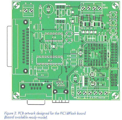
1. Power supply. Once the PSU parts are installed, test that 5 V and 12 V exist and the PSU LEDs D2 and D3 light up.
2. All SMD resistors, capacitors and remaining LED’s.
3. All small-outline ICs.
4. All remaining pin-thru-hole (leaded) parts.
We recommend fitting the 74HCT541 and the 74HCT14 in sockets.
Once the board is fully populated, apply a power supply of roughly 15 VDC to Kl and confirm that the PIC18F!ash board draws a quiescent current of around 50 mA. Once the board has powered up correctly, it is time to attach an LC display, flash the CPU and test each subsystem on the board.
Flashing the demo firmware
Traditionally, one writes and loads a ’flash-an-LED’ or ’Hello World’ program to test a microcontroller board. Here, a successfully blinking LED confirms that the CPU is powered, has a viable clock, and is executing code. We have provided self-test firmware which not only flashes LEDs but also exercises the serial port, the sounder, the LCD, the MOSFET switches, the H-Bridges and the real time clock. The constructor should upload this demo firmware, PlCl8flash.hex to the microcontroller using the IC-Prog programming software to fully test the PCB. The source code, PIC18Hesh.c can then be used as a template for further developments.
Configuring IC-Prog
Download the archive files icprogi05c.zip and icprog_driver.zip from www.ic-proa.com and extract icprog.exe and icprog.sys to a suitable folder on your hard drive.
If you are running Windows 2000 or Windows XP, you should enable access to the parallel port as follows: right click on icprog.exe, and select the Compatibility tab. Check the .Run this program in compatibility mode for option and select Windows 2000 in the drop down box: see Figure 3. 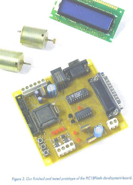
Now run icprog.exe and you will be prompted to configure the programmer interface: see Figure 4. 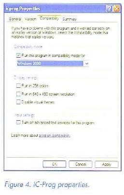
Select Settings. Options. Misc and select the Enable NT/2000/XP Driver checkbox, and set Process Priority to High: see Figure 5. 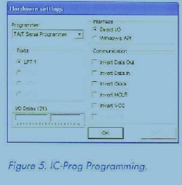
Click ’Yes’ to install the icprog.sys driver when prompted and finally select the PIC18F452 microcontroller type as shown in Figure 6. 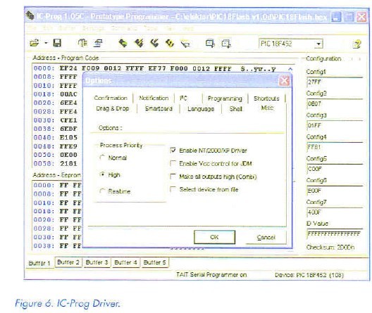
Reprinted Url Of This Article: http://www.seekic.com/blog/project_solutions/2011/08/12/PIC18Flash_development_Board__Continuing_where_the'16_series_left_off__(2).html
Print this Page | Comments | Reading(1089)
Article Categories
New published articles
· Imagination works with TSMC to develop FinFET process
Author:Ecco Reading(30201)
· XMOS pushes event-driven MCUs with lower price
Author:Ecco Reading(3462)
· Intel brings upgraded 32-nm SoC for smartphones
Author:Ecco Reading(3182)
· Micron pushes TLC 128-Gbit NAND flash
Author:Ecco Reading(3662)
· Intel will stop supplying desktop motherboards
Author:Ecco Reading(5233)
· Processor market was expected to regain strength in 2013
Author:Ecco Reading(3249)
· It was reported that TSMC sales fall steeply
Author:Ecco Reading(3390)
· Cisco, NXP work with auto wireless startup
Author:Ecco Reading(3531)
· Micron was impacted by manufacturing glitch
Author:Ecco Reading(3936)
· China can make 22-nm transistor by themselves
Author:Ecco Reading(3708)
· Chip market rebound is coming, according to survey
Author:Ecco Reading(3678)
· Sony, Toshiba will spend more on chips, iSuppli reports
Author:Ecco Reading(3715)
· Qualcomm becomes the 13th company to join NFC Forum board
Author:Ecco Reading(6029)
· TSMC increases building work for FinFET fab
Author:Ecco Reading(3693)
· TI plans to cut 1,700 jobs in OMAP shift
Author:Ecco Reading(4479)