

Project Solutions
PIC18 Flash development Board: Continuing where the'16 series left off (1)
Published:2011/8/12 0:49:00 Author:Li xiao na From:SeekIC
By Peter Moreton
The development system described in this article continues a fine tradition of Elektor Electronics microcontroller articles, and follows in the lineage of the popular PICee board, AVRee and others. The board described here employs the most recent and powerful of Microchip’s PIC family, the ’1 8F’ series, and specifically, the PIC18F452.
The PIC18F4b2 has become the defaczo standard part of the I8F series. and is an obvious choice for people wishing to move on from designs using the ubiquitous PICI6F84 and 16F877 devices.
PIC18flash offers the usual development board features of a processor. clock, some LED’s. some pushbuttons, an interface to a standard 2’20 line LCD display, an RS232 port, a piezo ceramic sounder and DC power regulation. Special features are:
- On-board hardware for ICSP (in-Circuit Serial Programming)
- Power I/O for real-world devices such as solenoids, stepping and DC motors.
- An interface to the Microchip ’ICD-2’ debugger
With this hardware, the free Microchip ’MPLAB’ development environment and a free demonstration copy of the ’C!8’ compiler, you are able to develop PIC ’C code on a standard PC, and upload it to the PIC18Flash board to build sophisticated control systems for many applications including robotics,home automation, security and more. A ’C18’ example program is provided, demonstrating how each subsystem of the PIC 18Fiash board is accessed from the ’C environment. As a self contained development environment, the PICi8Flash board provides an excellent platform for educators and "individuals wishing to enter the world of microcontrollers.
Circuit Description
The circuit diagram of the development system is shown in Figure 1. Much of the circuit techniques will be quite familiar to Elektor Electronics readers, and the 78xx-based power supplies (IC1; IC2, IC9) and MAX232 RS232 serial interface (IC5) constellations have appeared countless times beforehand. 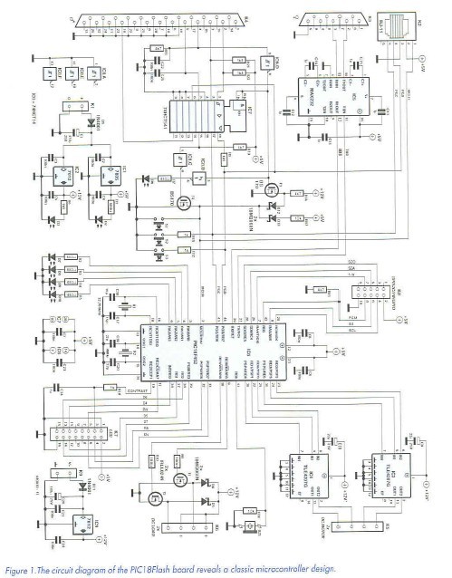
The PIC18F452, IC6, is configured in a standard manner, with the possible exception of the secondary 32.768 kHz watch crystal, XI,being provided to allow real-time clock systems to be implemented without consideration of the master clock frequency. The master clock runs at 4 MHz (X2), giving a throughput of 1 MIPS, and this can be internally multiplied by a 4*PLL to 16 MHz. which results in a processor throughput of 4 MIPS. Users requiring still more performance can substitute a 10-MHz crystal, giving 10 MIPS when used with the 4xPLL.
The 4 MHz ’fosc’ value is not chosen arbitrarily; this clock rate is a good ’fit’ with the PIC’s USART baud rate generator and enables the generation of RS232 data at 1.2 to 76.8 kbps with an accuracy of better than 0.16%. Processor pins assigned to SPI and I2C communications are routed to header K8 for expansion purposes; it is intended that any add-on hardware would communicate solely by these protocols and any communication to a host computer would be via RS232. The SPI/I2C header also delivers a spare processor pin (W; pin 7 on K8) which can be used for example to bit-bang other protocols such as the Dallas One-Wire interface.
In order that the PIC18Flash can perform some real work, the basic board is equipped with several power devices intended to permit the control of relays, solenoids, lamps. DC motors and stepper motors. Two separately powered Infineon TLE4207 H-bridges. IC3 and IC4, are provided, which permit the bidirectional control of two DC motors, or one bipolar stepper motor. Two power MOSFET switches are also provided. Via connector K6, they can be used to control resistive or inductive loads such as solenoids and lamps.
A pinheader, K7, for the ubiquitous 2?20 character LCD module is provided, and this is configured as a standard 4-bit interface, with the only unusual feature being the use (via the RC2 line) of the PIC’s PWM module to provide software control of display contrast.
Finally,an RJ-11 header, K2. is provided to enable the use of Microchip’s ICD-2 in circuit programmer / debugger, which enables the target hardware to be debugged in real-time. The user should take care not to use the onboard (MTSP) programmer and the ICD-2 interface at the same time!
Reprinted Url Of This Article: http://www.seekic.com/blog/project_solutions/2011/08/12/PIC18_Flash_development_Board__Continuing_where_the'16_series_left_off__(1).html
Print this Page | Comments | Reading(1447)
Article Categories
New published articles
· Imagination works with TSMC to develop FinFET process
Author:Ecco Reading(30193)
· XMOS pushes event-driven MCUs with lower price
Author:Ecco Reading(3462)
· Intel brings upgraded 32-nm SoC for smartphones
Author:Ecco Reading(3181)
· Micron pushes TLC 128-Gbit NAND flash
Author:Ecco Reading(3662)
· Intel will stop supplying desktop motherboards
Author:Ecco Reading(5231)
· Processor market was expected to regain strength in 2013
Author:Ecco Reading(3248)
· It was reported that TSMC sales fall steeply
Author:Ecco Reading(3390)
· Cisco, NXP work with auto wireless startup
Author:Ecco Reading(3530)
· Micron was impacted by manufacturing glitch
Author:Ecco Reading(3936)
· China can make 22-nm transistor by themselves
Author:Ecco Reading(3707)
· Chip market rebound is coming, according to survey
Author:Ecco Reading(3678)
· Sony, Toshiba will spend more on chips, iSuppli reports
Author:Ecco Reading(3714)
· Qualcomm becomes the 13th company to join NFC Forum board
Author:Ecco Reading(6028)
· TSMC increases building work for FinFET fab
Author:Ecco Reading(3692)
· TI plans to cut 1,700 jobs in OMAP shift
Author:Ecco Reading(4478)