

Project Solutions
PICXEX18 AND PlCWIN8- Operating System and Monitor for PIC Microcontrollers (2)
Published:2011/8/12 1:44:00 Author:Phyllis From:SeekIC
By Lourens le Grange
In Figure 1 the operating system’s ’task activation code’ is a single CALL TASK_X instruction. This will have to be extended. Firstly we need to add a test to prevent a task from being activated if it is switched OFF. Secondly we must be able to change a task’s entry point during runtime, in which case a CALL instruction cannot be used as the destination address of this instruction is fixed at assembly time. 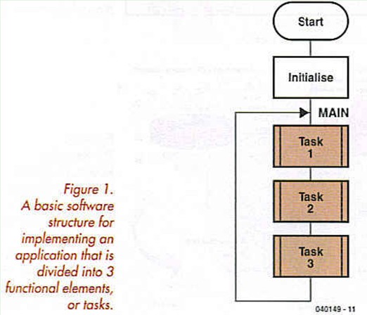
The ON/OFF test for a task is implemented by assigning a bit variable to each CYCLE TASK, which if set, will indicate that the task is in the active state. The facility to modify a task’s entry point is implemented by using the PIC1 8’s ability to push an address on its return stack. So the CYCLE TASK activation code needs to first test the task’s ON/OFF flag, if it is set then get the task’s current entry point value, push it on the Return Stack, and execute a RETURN instruction.
For each CYCLE TASK 3 RAM bytes are reserved. The first byte holds the ON/OFF flag in its Bit<7>, and the next two bytes the task’s current Entry Point value.
Application design can be further simplified by adding to our operating system the ability to execute tasks at selectable time rates. This allows the programmer to concentrate on the task code itself without having to be concerned about how to code timing or counting mechanisms to regulate execution of that code.
PICXEX18 allows for 8 TIME TASKS with the execution rate of each task being set at assembly time in the file xextaskl .def. As their execution depends on time these tasks cannot be switched ON or OFF by the user, and their entry points cannot be modified. PICXEX18 uses a CALL instruction to activate a TIME TASK. This allows for a simple activation mechanism — if the task’s ON/OFF flag is set then CALL the task’s code. To pass control back to the operating system the programmer uses the Xex-TaskExit macro inside the task code. If you look at the actual code for this macro you will see that a RETURN instruction will do the same job. Using the macro is just a better way of indicating in your code where the task’s exit point is.
The basics of the PICXEX18 multitasker can now be described by referring to Figure 2. Before a CYCLE TASK is activated a test is made to determine if there are any TIME TASKS waiting to be executed. If there is, then control is passed (with a CALL MAIN01 instruction) to the code in Figure 3. 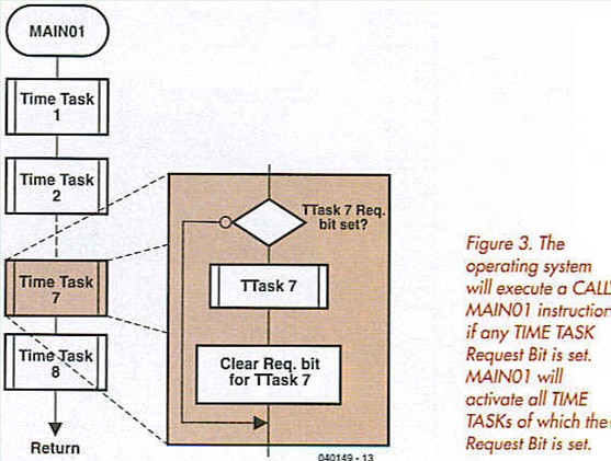
Here those TIME TASKS, of which the Task Request Bits are set, will be executed. At the end of the TIME TASK list is a RETURN instruction, which will take us back into the CYCLE TASK loop of Figure 2, so execution of CYCLE TASKS carry on from where it left off. 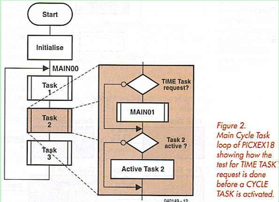
As shown in Figure 2 we test for requests to execute TIME TASKS between the executions of CYCLE TASKS. It is therefore important for CYCLE TASKS not to retain control of the CPU for longer than about 5 ms. A PIC running at a modest 8 MHz can get through a lot of code in 5 ms! A scheduler subroutine in PICXEXl 8 controls the activation of TIME TASKS by setting the Task Request Bits at the required times.
For the scheduler to function your code must provide for a timer routine to CALL the scheduler subroutine every 10 ms.
Reprinted Url Of This Article: http://www.seekic.com/blog/project_solutions/2011/08/12/PICXEX18_AND_PlCWIN8__Operating_System_and_Monitor_for_PIC_Microcontrollers__(2).html
Print this Page | Comments | Reading(648)
Article Categories
New published articles
· Imagination works with TSMC to develop FinFET process
Author:Ecco Reading(30193)
· XMOS pushes event-driven MCUs with lower price
Author:Ecco Reading(3461)
· Intel brings upgraded 32-nm SoC for smartphones
Author:Ecco Reading(3181)
· Micron pushes TLC 128-Gbit NAND flash
Author:Ecco Reading(3662)
· Intel will stop supplying desktop motherboards
Author:Ecco Reading(5231)
· Processor market was expected to regain strength in 2013
Author:Ecco Reading(3248)
· It was reported that TSMC sales fall steeply
Author:Ecco Reading(3390)
· Cisco, NXP work with auto wireless startup
Author:Ecco Reading(3530)
· Micron was impacted by manufacturing glitch
Author:Ecco Reading(3935)
· China can make 22-nm transistor by themselves
Author:Ecco Reading(3707)
· Chip market rebound is coming, according to survey
Author:Ecco Reading(3677)
· Sony, Toshiba will spend more on chips, iSuppli reports
Author:Ecco Reading(3714)
· Qualcomm becomes the 13th company to join NFC Forum board
Author:Ecco Reading(6028)
· TSMC increases building work for FinFET fab
Author:Ecco Reading(3692)
· TI plans to cut 1,700 jobs in OMAP shift
Author:Ecco Reading(4478)